Thanks everyone for your suggestions. I went with the resistor route since it will be less prone to future failure. Once I removed the LED and soldered in the resistors, I was back in service!
I did the fix above with three parallel 10ohm 1 watt resistors to replace the led. This fix worked great. Thanks to all for the great detective work. You would think the company could issue a firmware fix if this some sort of current limit issue from the led characteristics changing.
This is awesome!
I took mine apart yesterday. the LED sometimes flashes, but is dimmer than it used to be, so am going to try this.
I can solder circuit level, but do not have the skills to diagnose. Ordering LED now, will give that a try. Would like to also order resistors/diodes if I decide to go that route.
timnord (and tscan): I want to go the LED route, but if one wanted to permanently go the route of resistors/diode, could you list the part numbers, and/or resistor values, including power (watts).
Using three 10 ohm resistors in series worked for me too. Thank you for saving my garage door opener 
I got the pack of resistors from here https://amzn.to/2E0uAWM
Can someone post a tutorial with picture or video how to remove, replace and solder the LED? I have a hard time following. Thanks.
Thanks to everyone in this post who figured this out! Was able to fix the opener (after I got the polarity right lol) by replacing the LED
TSCAN - thanks for posting. This worked perfectly. Even saved resisters for when second garage door fails.
You’re welcome!
Thanks to both of you for your work on this. My light doesn’t flash but everything else is working so I suspect I have the same issue. I’m going to wait until some warmer weather before tackling mine I think though.
Was also wondering if anyone had experienced repeat failure after either replace the LED or with the resistors.
Mine is still working after the posted modification.
Thanks for punching through this failure. I was able to use 3 - 10 Ohm resistors and mine is working fine now.

1 Like
Anyone think any reason this wouldn’t work ok? It’s a 3.3ohm, 5W resistor…
https://www.alliedelec.com/product/vishay-dale/cw0053r300je12/70201393/
Still cost $6 to ship, but easier to solder…
Same issue as everyone else here. I have virtually zero experience with soldering and resistors, but I will give it a shot.
The thing I noticed in the pictures is the stripes on the resistors are in an alternation pattern. Does this matter? Or does any orientation work?
Thank you for giving me reason for being optimistic for fixing this issue!
Resistors don’t have polarity - they’ll work the same either way you install them. The stripes are a code that tells the value of the resistor.
1 Like
Awesome, thank you much! Here goes nothing. 
1 Like
Hello everyone…
Like many others, nearly the exact same timing and mine stopped working with the same symptoms.
We tried the timnord solution this past weekend. Strange thing… now my garage door is opening again (via the app, or my smarthome routines, etc.) but I can’t get it to close. Really odd. I figured if this fix addressed the issue for opening, it would also address it for closing.
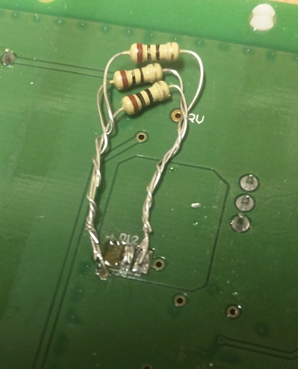
We experienced a bit of a problem when removing the LED. I think one of the metal pads under one of the sides of the LED got too hot, and when we popped the LED off, it came along for the ride. After messing around with a multimeter and checking continuity and making some guesses, we figured we could just solder one side of the three-resistor cluster into the tiny hole next to the now-absent pad. The other side of the resister cluster is on its pad per timnord.
I’ll put a couple pictures up so you can see what I mean. If anyone has any idea why this fixes the opening but not the closing, I’d love to hear it.
Thanks!
(All steps are optional ).
- Remove resistors and unwind the leads.
- Call one of the resistors say, Primary. The other two will be Secondary.
- Cut leads of the Secondary resistors to say, 1/2 of the original length.
- Rewind the Secondary resistors’ leads onto Primary (keep the resistor bodies together).
- SOLDER the joints. Tin ends of the Primary resistor leads.
- Remove solder from the LEFT hole. (Solder wick + toothpick). To remove solder from the hole, you may need to add some solder first.
- Inspect area carefully. If necessary - use x-acto knife.
- On the PCB Component side: Insect the hole pad. Most likely, it’s covered with coating. VERY carefully scrape the coating with x-acto knife. Clean with alcohol.
- Feed the Primary resistor lead through the hole.
- Solder from the Component side. Do NOT overheat - the trace will peal.
Sure appreciate the response and help!
Couple questions for you:
-
In regards to shoving the primary lead through the hole and soldering from the PCB side, is your thought that there’s not a good connection right now?
-
And is the purpose of trimming the secondary resistors’ leads back simply to uncomplicate things, or ensure only one is going through the hole?
-
Are you leaning towards thinking that a poor connection might be leading to only the door opening instead of both opening AND closing?
Thanks again!
Yes to all three
You said that you may have overheated the trace. When the latter happens, connections between traces and the feed-though get compromised. Given that the replacement resistance is in low ohms, everything counts.
Of course, if you can confirm that your replacement connections are reliable and stable, the exercise is not needed.
I do not know much about the design but assuming GoControl put some thoughts into what they were doing, I would not be surprised but the observed door behavior.
And of course, this all is a wild guess:)