Question about the wiring of the GE zwave switch for 3 way.
Says I need the add-on switch which is fine.
My main question concerns the wiring. Says I need the line, load, traveler, neutral, and ground. (Ignoring neutral and ground for my situation)
Switch box 1 just has the line and traveler. Switch box 2 has the traveler and the load.
Can I install the switch in box 2 and just hook up the traveler as the line? Then wire the line to the traveler terminal for the add-on switch in switch box 1?
Basically my issue is that the line and load are not in the same box.
Well, a typical 3-way has to run at least 2 wires between the two boxes. Usually, they run three between them. (Red, black and white)
If you have three wires between them, you should be able to do what you need to do. If you only have two wires, you’re going to use an add-on switch that works with Z-wave association, rather than a traveller wire. (Like the Linear switches.)
The other problem you might run into is if the switches are just a switch loop. In that case, the power comes in up a the light and it only runs the hot wire down to the switches and back up to the light. In this case, you cannot use z-wave switches in the wall at all, and instead need to use something like the Aeon module:
Just found that I believe this is how it’s wired. I haven’t confirmed if the white wire goes between the the 2 switches. I’m assuming it does. It’s in a box with another switch that I could grab a neutral from.
IF that is how it is wired, you have everything you need.
IF that is how it is wired now, I would put the standard switch in the left box, the white wire on that switch would wire together with the three white house wires (from the panel, to the light and to the other switch box).
Then, I would wire the line side of the switch to the black wire from the panel and the black wire to the other switch box.
Then, I would wire the black wire to the light to the load side of the switch.
Then, I would wire the red wire to the traveller connection on the switch.
Then, in the other box, I would wire black and white where you would expect them, and red to traveller.
But, you really need to make sure that is how it is wired…
The add on switch goes in the box to the load. Take the traveler (red wire) and put on the traveler port of the add on switch. Wire nut the two black wires together. hook up the neutral and ground to the switch, and you are done there.
In the other box, use the 12722. Line and neutral on the bottom holes. Traveler (likely red) goes on the taped cover terminal, marked no 120v. Then the other black wire goes to the Load connector. (this is because you wire nutted the load to that black wire in the other box).
I should clarify, in the picture I posted, the line coming in from the panel is actually in the box on the right.
bamarayne
(Jason "The Enabler" as deemed so by @Smart)
7
I ran into this same problem. I had a three way switch with the load in one box and the line in the other. I put the Aux switch in the box with the line and the Primary switch in the box with the load.
The setup had a 3 wire romex running between the two boxes. I used on for the Line to go from box to the other (black) one for the traveler (red) and one for the neutral (white).
I just had to tie the line in from one box to the other and it wasn’t a problem. Though it took me about an hour walking back and forth between the two before I finally figured out what I had.
If so, you put the main switch in the box on the left and the aux in the box on the right. In the aux box, take the two hot (black) wires and wire nut them together, not connected to the aux switch at all. This gets the load back to your main box.
It very well may be that… there is a white wire hooked up to both switches which may be there instead of the black between the switches(I don’t think its the neutral)… odd why it would be a white and not black. Guess I will do more investigation after xmas.
bamarayne
(Jason "The Enabler" as deemed so by @Smart)
11
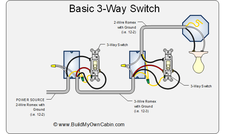
This is the exact diagram I used to figure mine out. It’s all coming back to me note that I’ve seen the picture.
My problem was that I had a 2-wire romex running between the two boxes. The electrician installed the wrong romex. So instead of running new romex he colored the white wire black and used it as the black line between the two switches. Luckily there were other switches in my boxes.
It was a real PIA to figure out.
I ran a neutral from each switch into the neutral bundle in each box. I tied the line and load together in the box on the left and used the colored white wire as my traveler. My aux switch is in the box on the left and the primary is on the right.
hmm, look real good at the white wires and see if they have any black tape or black marker on them. If so, they are definitely hot and that diagram won’t work. If they don’t, you probably need to check with a multimeter if they are hot. If they are just regular builder grade switches and have a white attached to the switch itself (not jsut in the box) there is a good chance they are hot.