So I’m pretty sure I’ve read through every single Aeon Smart Dimmer thread and have yet to comprehend the wiring configuration. I think I’m close, but I’ve already fried one dimmer and don’t feel like frying a 2nd. I’m not sure how they are supposed to connect to the switches and I’m not comprehending the Aeotec diagrams (if only they would label everything).
I have 14/2 coming in from the breaker to the 1st switch
14/3 running over to the 2nd switch
Here is what I have in my head… I have no idea where that red traveler in the 14/3 is supposed to go
I don’t think that’s right, I don’t have the drawing I used on me. I thought there was 2 wire connections between the switches and one wire from each switch to the micro.
I’ll have to go look at the drawings and look at how I wired mine. It took me alot of checks with meters and rewiring to wrap my head around it. (Just the adding the 2 switches part)
See if this diagram helps you out. You can abandon the red wire and cap it off. You only need two conductors to be used into the Aeon.
Things to consider:
take detailed pictures and label your wires so you will know how it all worked before you started in case you need to go back and verify what is what.
your 3-way switches are rewired to be simply inputs to the Micro Dimmer in this new smart wiring. You must have the newer Micro Dimmer G2 model.
determine and label what you incoming power is from breaker so you can terminate the black hot to AC Power L terminal. The white neutral to AC Power N terminal.
determine which wires go out to the load (lights) which connect to LOAD L and LOAD N
consider modifying the Decora-style switch to be momentary and not latching so you can actually dim up and down the lights as well as turn off-on. This is the recommended external switch for the Micro Dimmer, you can hold down the momentary push button to dim up or dim down the load. Or you may tap the momentary switch to turn it on/off. If you have the Aeotec Micro Smart Energy Illuminator G2, it is set to be controlled via 2-state(flip/flop) external wall switch by default. Pushing and holding the button 6 seconds on the Micro Smart Energy Illuminator G2 will swap between this default mode and the momentary push button external wall switch mode.
Depends how it is currently wired. When I did mine I did not have to add any romex runs or wires. I did have to rewire it MUCH different than it was before. I also had to use short pieces of 16ga wire to connect the wall switch wires to the micro switch connections. My line,load,and neutral were in the light box so was easy to hook up the light part.
You NEED to open the switch boxes and the light. Trace the wires, Mark the wires, take pictures BEFORE you unwire anything to do your checks. Figure out which Romex run goes where. I then labeled the wires as I figured out where they went. Then marked up a printed drawing to show what I needed to hook up where.
Just my opinion.
There are other VERY knowledgeable electricians around that could help. They will still need to know what you have and how it’s wired efore they could offer wiring advice.
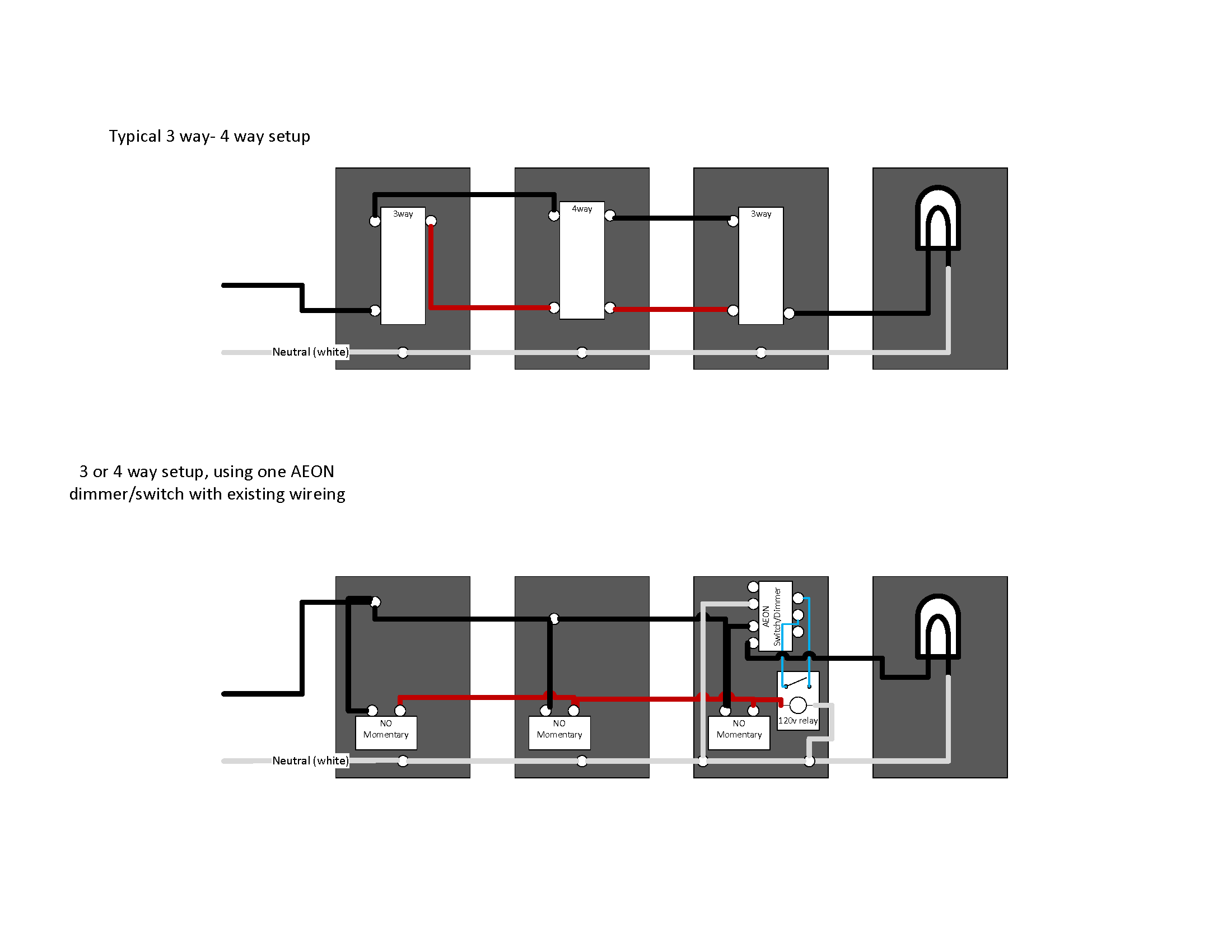
Ok, I think I have a solution. Each box has multiple switches in it so I think I can take advantage of the neutral that is running between the “normal” 3-way switches. Will either of these work? I tried to simply it in the 2nd picture, by not having to use any wires from the “normal” 3-way.
I’m in the same position. Will likely not be able to add the dimmer to my four-way switch set up without hiring an electrician and adding an additional wire.
This is the drawings I used when I did my 3 way circuit. I kept power off of the switches. Took me several checks and relabeling this drawing several times before I wired it up.