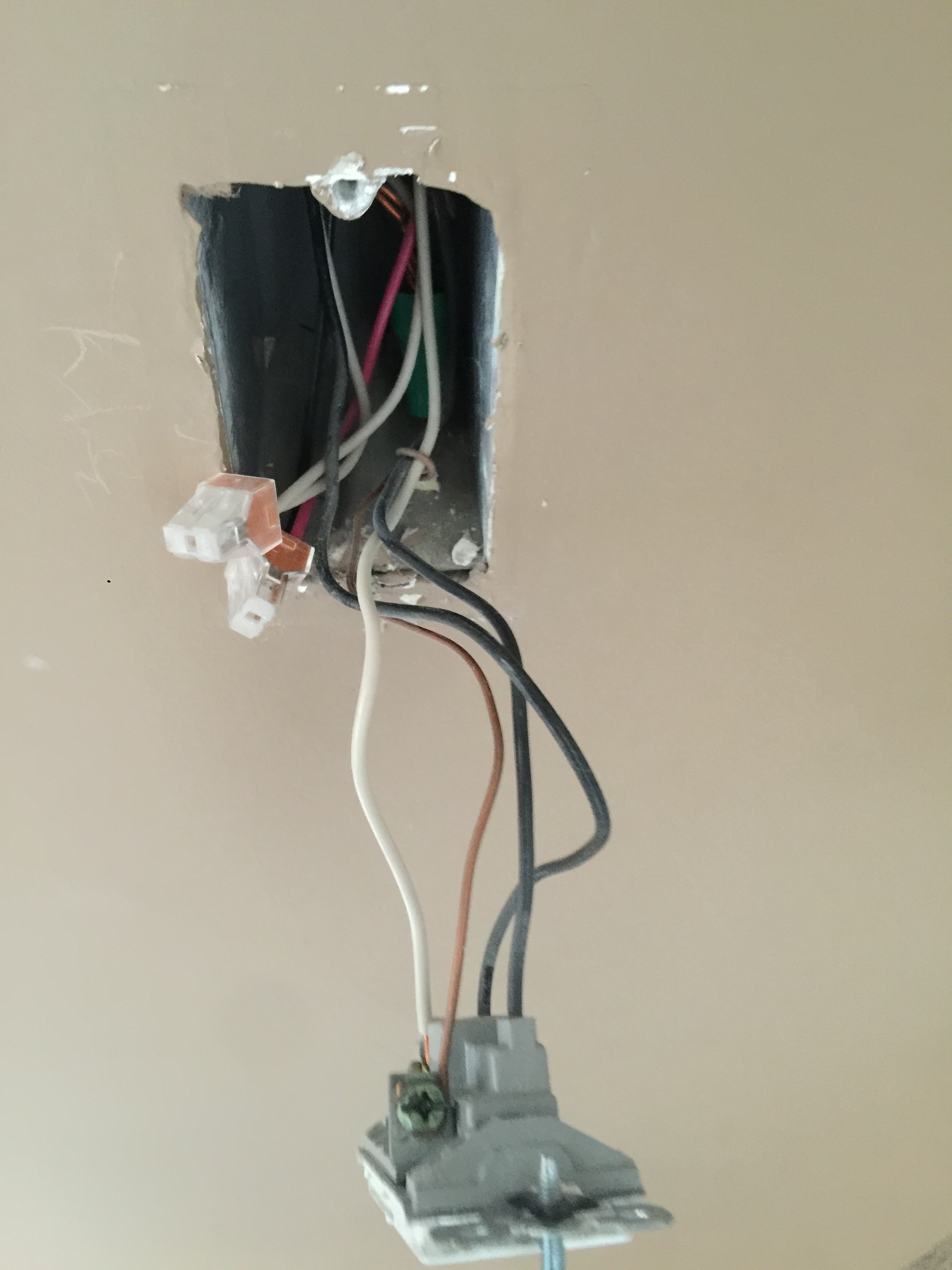
Hi - I have the GE 3-way switch and 2 add-on switches but my existing wiring appears to follow the following diagram with 2x3-way switches and 1x4-way switch. Is there a way to verify that this is in fact my wiring diagram and then how would I go about wiring up the z-wave switches?
Showing pictures will not help us help you. You need to determine what each line is and mark it as Hot, Neutral, Ground. Then once you have that done, you can start to determine the possible connections at play. I know we had a similar setup here at the house, and using GE 3-way switches. I had to determine which one was the master switch, then I made sure that the traveler was connected between each switch along with what was needed by GE to operate.
The problem is that I have found wiring from house to house depending on work done and the electrician (if any) is not always consistent. Normally Black would be ground or neutral, while could be ground or neutral, and red is normally hot.
Another way is to look up the switches in place, and see what the manufacturer states the setup is for each placed wire. That should give you a good start.
Otherwise, you can do a search here in the forums looking for 3-way / 4 - way setups for what others have done.
In my experience, black is hot, red is traveler, white is neutral, and copper is ground.
Edit: Reread, fixed: I have not seen white used as hot and I have seen red used as hot, but YMMV.
Best to do as recommended, take a volt meter (they are cheap) and write down what each line does with the switches in a position, then flip a switch and write it down again. Any wires that are always hot are line, any that are always 0 are likely neutral, and any that are sometimes on/sometimes off are either load or traveler.
That being said, I’m not an electrician, and not there, so good luck!
Yep, as I stated the line color is often not a good indication of what they do in a house. My house is a mix of old and new, the old side (no Neutral) the new side (as I noted above). The electrician did a nice job of wiring the new side of the house, but the old side to new side was a mess.
Hi Sean, look like you have a standard 4 ways circuit so this should be pretty straight forward ( I hope). You have both the load and line coming into your box A. This is just a guess but here are the wires. Box A
The black wire going into the common screw is your load.
The black wire that’s connected to the red wire is your line hot.
The Two white wires that’s connected together. That’s your neutral.
You can confirm the wires.
Load - disconnect the load wire going into the Common screw of box A and put + of your meter on the common screw of the switch and - to neutral. Now flip a switch. You should see voltage at one position and nothing at the opposite position. Leave the meter there and do that with the other 2 switches. Should be the same result. If that’s true then that’s your load.
Line hot - remove the black wire that’s connected with the red. Put meter + on that black wire and - to neutral. You should get 110v regardless of switch position. With that wire still disconnected. There should be no voltage at any other wire.
Here’s how you will hook up your z wave.
Red will be you traveler. Just need an extra pigtail wire for you traveler at box B.
Neutral. Tie all the white wires together at all the boxes and have a pigtail for your new switch.
You already know load and line hot. It’s at your box A and that’s where your z wave master will be located.
Remember to take pictures and Mark the wires in case you get struck and and to go back. Also don’t forget to turn off the circuit breaker and ground wire. Good luck.
Edit : the black wire going into your common screw.
I meant to say the common screw of the switch.