@Lgkahn - Can you give some detail as to how you wired the 9542 as a standalone switch? I just got some and want to make sure I do it properly.
it depends on your wiring… you just give the switch neutral and power and wire the load to the line so the light is always on… then you add the switch in smartthings as normal and use a smartapp to control the smart bulb
That’s what I would have guessed but when I connected to line after having ground and neutral wired it sparked unlike I’ve ever seen another switch do. I thought maybe it wasn’t designed for a full 120. I assumed I had toasted it but maybe I’ll try again if you’re saying that’s how yours is.
No you don’t attach ground to
anything. Just ground on the switch …look at the old switch. I believe line
Goes to load . And neutral to switch and line to switch.
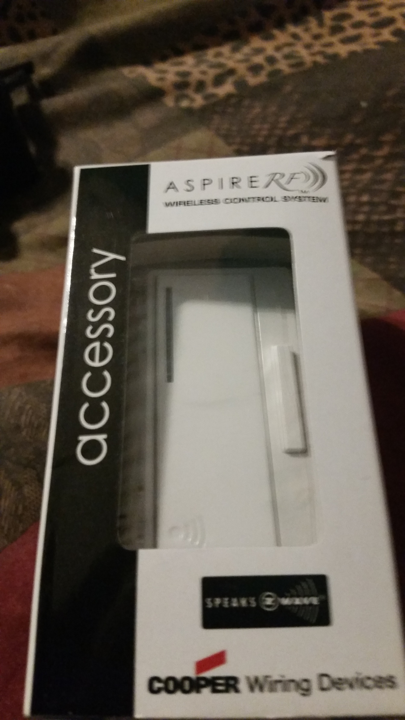
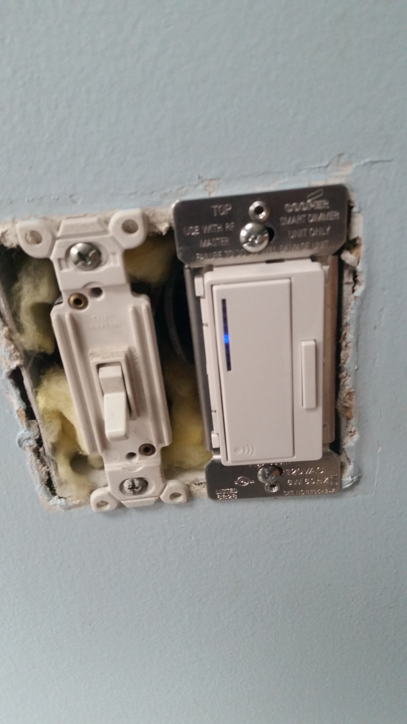
@Lgkahn Are we talking about the same accessory switch? Below is an image of the 9542 I have. I’m not sure why you wouldn’t want to ground it. However, I definitely fried the switch by connecting one blue wire to neutral and one to line. Did you wire both blues to line?

I have no idea what the switch you have there… it should look like mine… maybe you have the non rf version. There is a non rf 9542 that is not the same… it should have 3 wires black, green, white…
white goes to neutral. green goes to ground, black goes to line.
and you jumper line and load together… my guess is you have two green and you wired ground to the wrong green possible… you never wire ground to neutral…
there is also an older version I think that does not require netural… maybe you have one of those and that again is not the same switch.
see picts


1 Like
here is the wiring on one of mine… the black actually goes to a nut with 4 wires…
- is the line, 1 is the load, 1 is the black from the switch and the blue is a jumper from the line/power to the other switch in the box…

I’ll do more research…I’ve installed plenty of switches and rewired much of my house so while I’m,not an electrician I’m very well aware of how these things typically connect. I’ve seen this type of non-specific color coding in standard dimmer switches before but obviously there’s something different about this one. It’s definitely the RF version - in addition to that being obvious on the packaging there’s a big sticker around the connection wires saying not to wire it hot due to the radio inside. My best guess is that the switch is only designed to take low voltage over the traveler wires.
After more investigation it appears that this switch is designed to receive low voltage power from another switch with a -N designation in the model number.
Adding @JDRoberts since this came about in the deal forum a couple weeks ago.
I must be dim (see what I did there?) but I can’t figure out how to wire this accessory switch into the box while leaving the light’s circuit hot. I’m using the Gocontrol WT00Z5-1, not the Cooper referenced above but the switch wiring is the same. The switch needs ground, line and neutral. This would leave the load disconnected and would permanently disconnect the circuit if the load isn’t connected to anything, would it not? And if the switch only needs line, not load, then I can’t connect them both to permanently complete the circuit, can I?
First rule of home automation: the model number matters. Please do not post questions about other models in threads devoted to a specific model. In fact, the wiring is not exactly the same and the devices are not exactly the same.
In this case, because this is the newest model of that device and There have been yet some additional changes, I suggest you start a new thread, put the model number in the title, and then people can help you with the wiring there.
https://community.smartthings.com/c/devices-integrations/connected-things
Besides, a lot more people have the gocontrol model, so there will be a lot more people likely to help. 