Hello,
I have the GE 12728 and 12729 switches ready to install in one of my rooms in my house. The way it is wired, the light fixture is powered, so only have the load, line, neutral and ground wires coming in to the box(es).
MY primary switch will not have the ‘Line’ wire as if the power was coming onto the switch box. Sooo, can I use a ‘Line’ wire from another circuit for this purpose?
If power is coming into your light fixture box then what you are missing is neutral at the switch boxes. I don’t recommend using power or neutral from another circuit unless that circuit is using the same circuit breaker.
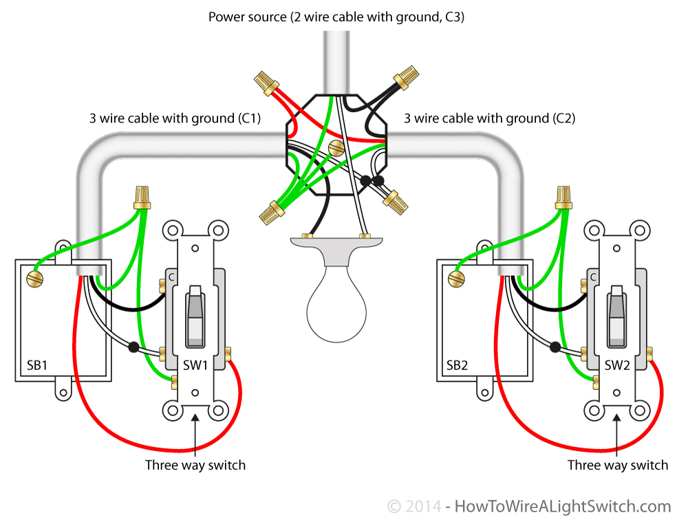
So here’s a picture of what my setup looks like… I could probably re-wire if necessary to make GE/SmartThings work (This would be the most important light circuit in my house), Just wondering if there’s a work-around. I have another light switch on the same circuit in the same box if that matters,
With your present wiring scheme you do not have a neutral at your switches but you do at the light. You have all the wiring necessary to rewire and make it work.
In order to get the switch to work you do NOT have all the wires necessary.
At the 12729 you’ll need 4 wires plus ground. You will need a LOAD line just as you probably excepted, but termed wrong. The load needs to replace the black wire at the light fixture and go to the 12729.
You also need
Line, the black wire already there
Traveler, the red wire again already there.
Plus you will need to wire the whites as neutral and remove the markings at all three locations. Remove the neutral wire from the light fixture. Take the two white wires with black tape remove the black tape. Wirenut them together with the white wire that came with your switch. Attach the end back to the light fixture. Remove black or markings from other two locations.
I have the line but no neutral on the other switch(same circuit). The other switch(single pole) is powered from the light fixture as well, so the line travels down from the bulb but the neutral is really the traveler going back to the bulb(s).
If you’re 100% sure the line to the other switch is on the same circuit. You could cap off the line at the light fixture(the one currently going to the switch) Take the black wire going to the main switch and wire it to the light fixture and to load at the other end. Tap into the line from the second switch.
Then white red and black as previously posted.
If @Navat604 has a different way, I would genuinely be interested. Sometimes you can’t see the forest for the trees.
I’m sort of fascinated by this as it seems to have gotten a bit confusing. The bottom line is this:
At the main switch (12729) you must have a wire that brings in your 120v (hot/black/line) and neutral (white) AND a wire that takes out the switched power (load) PLUS your traveler. So that’s why Kato said you need 4 wires there, which you don’t have. So for rewiring, you need to run an extra wire or run some 14/4 from the light fixture to your main switch.
He has 2 circuits on the same breaker with line at the box. By configuring the wiring at the fixture box. He needs only 3 wires from that circuit. The fourth wire is the line hot from the other circuit. Of course this will only be doable if there is access to the fixture.
Edit : by doing the above. You should be able to add GE smart switches for both circuits.
I would make sure that the “line” in the switch box is actually a line coming from the breaker vs. the line the is tied to the 3-way circuit which originates in the light fixture box.
Do this by disconnecting the source “line” at the light fixture box and then testing the switch “line” to see if it still has juice.
Seems odd that there would be 2 lines on the same circuit ran to the light fixture and switch. However, if there is, then you are in good shape and have all the wires you need as describe above.
Agreed. Especially in older homes that " handymen " have done work over the years circuits can be inadvertently tied together and if they are on the same Phase you may never know. You could have a circuit on two breakers and if they are both on Phase A you would need to turn off both breakers to kill the circuit.
The op said line hot from the same circuit breaker going to 2 different light circuits. Not 2 line hot going to the same 3 ways circuit. You will see this very common in older home actually. I think we are getting lost with terminology here.
There is no measurement required to know. Just turn both lights on and go shut off the circuit breaker.
So, last night I unhooked and tested everything. I know exactly which wire goes where, and it is basically what I had pictured above.
If my primary switch is on the right side of my picture, I have the load, line, and traveler wire that’s needed for 12729, but am missing the neutral wire, since it’s connected to my load. The primary switch will be in a 2-gang box that has a neutral line that I am thinking could be ‘shared’ with the GE switch. My reasoning is that all the white (neutral) wires have the same basic termination in the electrical panel, so they are all in essence ‘connected’ anyway. But after that I get confused…
Anyway, the GE manual calls the white wire from the breaker the ‘Jumper’… I can refer to it as ‘neutral’, correct? Now the jumper(neutral) needs to travel from my primary switch to my add- on switch, but since I basically have a hot and two travelers, I am missing that neutral wire. If you consider that all the neutrals are tied together at the electrical box, I could essentially mimic that wire by just using any wire that is a true neutral. Correct?
Even if all of that works…I still need to get that jumper(neutral) back to my light fixture That wire doesn’t exist in my romex- that wire/light fixture connection actually goes back to my electrical panel. BUT, since it is connected to the other neutrals at the electrical box, the connection should be there, just taking a different path. Do you get where I’m going, here? I’m tempted to give it a shot and see what happens unless someone can point out flaws in my train of thought. I just don’t want to burn out expensive switches while experimenting.
Absolutely DO NOT do this! You’ve just defeated the circuit breaker by giving an alternate path to ground. And that alternate path is the other neutral. So instead of having 15 amps going back on that wire you could have 30.