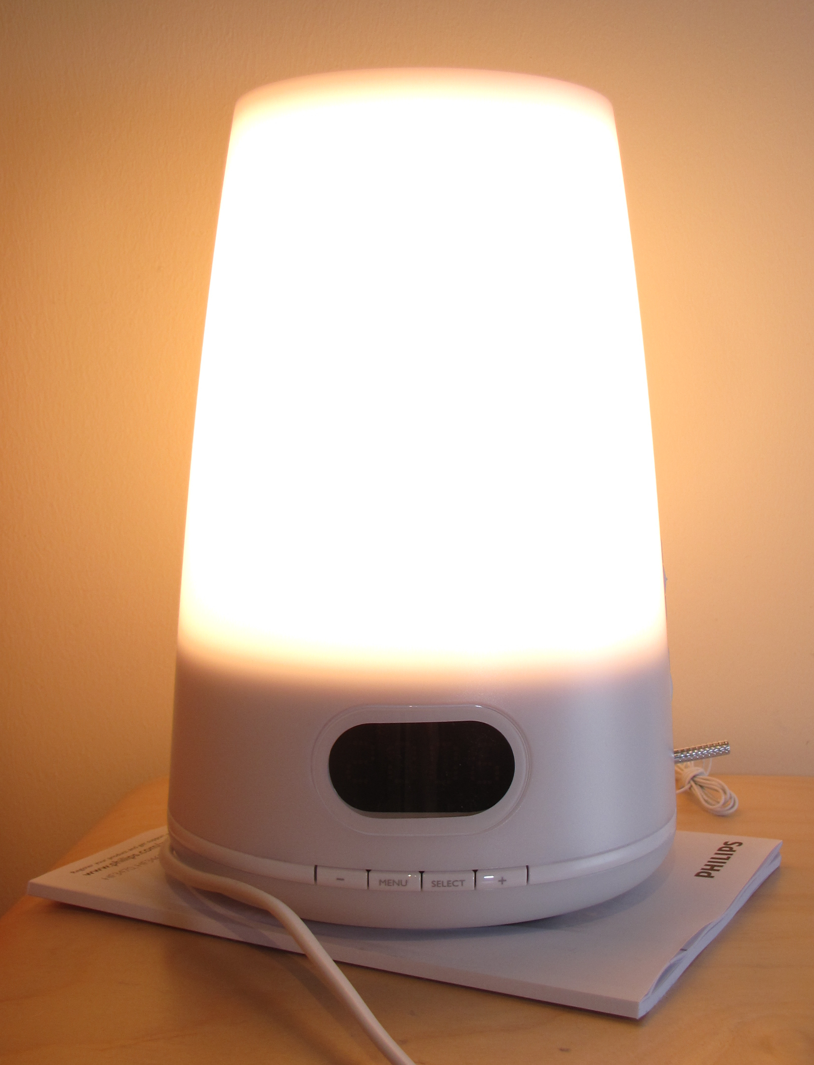
The Concept
A bedside alarm clock that is connected to the SmartThings zigbee network utilizing an Arduino Uno and the ST shield. It would not only be an input terminal for controlling other ST devices but be controlled by triggers from within the home.
Mimic the original function of the “wake up clock” by having basic alarm clock functionality that slowly increases the light as you near the alarm time. Tie into existing snooze button.
With an RGB light ring instead of halogen bulb, it would put you to sleep with more amber light at night that slowly dims, and the wake up light would be more of a blue hue to wake you up. (Blue/Amber light therapy)
Has motion sensor that can detect your movement in bed and wake you up or put you to sleep based on movment.
Has a speaker to wake you up at alarm time if you dont wake up based on light.
30 minutes before the alarm time (or your own threshold) it could turn on any ST switch or set any ST thermostat. For my application it would turn on the heater and my radiant flooring.
Has external control of RGB strip lighting. Mine will go under the bed frame.
Based on mode, if a motion or door sensor is triggered, it would make a sound and change LEDs to desired color. Mine will turn red if someone breaks into the house in night mode, and amber if someone breaks into my shed.
Utilizing the microphone, you can give it sound commands (clapping) to enter different modes or “scenes”. Like an intimate color scene of bedroom lights set to 15% and LED’s to deep purple when you clap 3 times.
Temperature sensor would give basic temperature reporting of the room to ST.
Thoughts on Future Extensibility
A replacement LCD screen that would display weather data when the alarm goes off.
Kickstarter it. If people are paying $100 for a Quirky Nimbus, I’m sure they’d pay more for something that gives a lot more features. You might want to consider adding some level of info display like the Nimbus. Nice idea!
I like! I was looking for something like this to alert me without waking up my wife if my older kiddo escapes from his room in the middle of the night.
Very cool. It has a lot in common with my project, the Smart Room Controller. We can talk about it on your thread or mine, but I bet your project would benefit from a custom PCB. I’m not sure if that’s something you were already doing, but I’m already planning most of those sensors for my PCB.
thanks @dome!
I was inspired by your project back at the end of june and thought some of those basic functions would do very well on my night stand. The alarm clock function is the core of my design with the other color and alert controls as secondary. We can comment and update wherever is most relevant at the time, Im flexible
Instead of using MOSFETS on board of the Arduino to run the PWM to the LED strip, would it be possible to use the dimmer module that came with the power strips, cut off the IR receiver, and hard wire it to the arduino and sent it signal that way? This way the power handling is offloaded to the factory dimmer module?
Just a thought. And it would free up 2 pins on the arduino
@docwisdom I think that could work. However, I wanted to build my own LED driver into my project for these reasons:
Cheap, since it’s only a matter of including 3 mosfets, a few resistors, an ATTiny85 chip, and a pin header.
Better quality control: I don’t know if I trust cheap components to push 5 amps to an LED strip. This way, I know the rating of the components I use.
More specific control: I can do things such as the red/blue alarm flash with the ATTiny85 that wouldn’t be possible with a conventional LED strip driver. Since it runs its own code, it’s very easy to customize.
Add sound: I actually run the piezo element off the ATTiny85 as well. It seemed cleaner, and that way audio and visual feedback could be in sync
Pin savings: The main Arduino ATMega328 only uses one pin to control 3 light channels and one audio channel, since it sends simple serial commands to the ATTiny that are in turn executed independently on the Tiny.
I don’t know your comfort with electronics, and programming on the ATTiny85 is a bit more involved than simply plugging in an Arduino. I think it’s well worth the extra effort, however, and would be more than happy to help in any way I can. I even made a programming shield that plugs into an Arduino’s headers and makes programming the Tiny as easy as programming any Arduino.
All that said, I don’t know your reasons for wanting to use a conventional LED driver, and it might make sense for your project where it doesn’t for mine. If you do get it working by bypassing the IR port, I’d be curious to see how you did it.
Very good points! You have easily swayed my opinion with point #3
I purchased an ATtiny with my last adafruit order. Ill havent had a chance to play with it yet. I also got a real time clock for the alarm clock function portion.
@docwisdom Glad I could win you over. I used this tutorial and this one for getting going on programming the Tiny. If you want to use my programming shield, here is a Fritzing file. It uses SMDs, but if you don’t work with SMDs it should be easy enough to change to THT components.
Even aside from this project, Tinys are great because they allow you to shrink Arduino projects. When you don’t need more than 5 IO pins, they are usually able to do the trick. The software serial library is needed if you want to use the Tiny as a coprocessor (as I did).
@docwisdom
I really enjoy this project, its the closest I’ve been able to find on the internet to a project I am trying to do. Does any of the controls connect to a phone app?