Adventures in 4-Way GE Smart Switch

I decided to automate my living room lights. My living room light is a single light with three in wall switches.

First, it would be nice if the Z-Wave manufacturers would be clear that you need “add-on” switches for this application.
I initially purchases a Z-Wave switch with the intention of swapping out an existing switch - alas, I found this would not work - since the other two switches were standard.

I used GE Dimmer and GE Add-on switches.

Here is my configuration.

left switch was a 4-way
center switch was the power
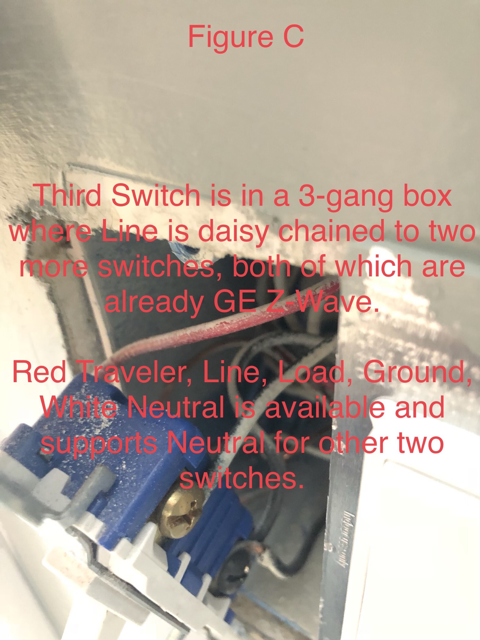
right switch was the load

As many may already know, the center switch takes a live line and switches it. you then have two “travelers” that go between the four-way switch and the load switch to flip power from one leg to another.

So the normal configuration is a bit complicated, but fairly easy to understand.

The “add-on” switches were a head scratcher. How do you go from five wires to 2???

The key to the whole thing were several posts that stated.

  1. Add-On switches will NEVER carry the load
  2. Add-On switches will NEVER carry the line (power)

So… this means I had to do some rewiring…

Step 1. Find the line in - obviously you need power (at all times) for your connected switch to function.
So the Z-Wave dimmer switch will be wired with the line in spot.

Step 2. Find the “live” line in wire and insert it into the switch. Wire in the neutral and ground.
Now you should have two wires left. Pick one to be you “load” carrier and mark it. The other will become the “traveler”

Step 3. Find the “load” carrier wire at you light in wall switch. twist the light and the load together - it will no longer be “switched” at that outlet.

Step 4. Wire in a “Add-On” switch at the load area, use the “traveler” wire you selected, and add the neutral and ground.

Step 5. At the 4-way switch, wire both “traveler” wires together on the same terminal, add the neutral and ground.
Twist the two “load” wires together - they will no longer be “switched”

Should be done now.

In my case, the 4-way switch did not exactly have a neutral - it was simply two wires from each switch - the line switch and the load switch. But… I was lucky enough to have a spare wire in the wall - I just needed to verify if the wire actually did anything - it did not. So I connected the spare wire to a neutral in the line outlet and I was good to go.

I have photos - but hopefully this description helps someone along.

2 Likes

Nice writeup.

I did a 4 way switch to my living room fan using the Aeon Labs Aeotec Z-Wave Micro Dimmer, 2nd edition.

It is a single module that I installed into the box behind one of the switches. I was able to keep all my existing switches. Pretty easy to wire in to a 3 or 4 way switch, and it only costs $35.

I created a login just to say that this write up was exactly what I needed, I just replaced a couple 3 ways and a 4 way with ge switches and add on and this was what explained what needed to be done, thank you!

If I have a 4-way switch that controls two lights in my two-story foyer, a chandelier and a flush mount in the ground floor hallway below and I want to switch them over to Z-wave switches, what do I need to do? My house is 13 years old, I am the first owner, but I hate electricity.

I have two ZW2002 Aux Switches and one ZW4001 Relay Switch.

My three current switches:

Figure A - The upstairs switch has what looks like a 4-way switch to me. This switch has 2 Red Travelers, 1 Line, 1 Load, a Ground, and the White Neutral lines are tied off in the back of the box. The switch next to it is a separate 4-way switch for another light.

  1. Which switch should I use for this one?
  2. Do I tie the Black Line and Load wires together with a wire nut or do they go into a switch?
  3. I assume the White Neutral pigtail to connects the switch to the white lines.
  4. I assume the two Red Travelers are used.
  5. I assume the Ground is a given.

Figure B - The hallway switch has a normal switch. This switch has 1 Red Traveler, 1 Line, 1 Load, a Ground, and the White Neutral lines are tied off in the back of the box. The switch next to it is is the only one in the box.

  1. Which switch replaces this one?
  2. Do I tie the Black Line and Load wires together with a wire nut or do they go into a switch?
  3. I assume I add the White Neutral pigtail to connect the switch to the white lines.
  4. I assume I use the Red Traveler.
  5. I assume the Ground is also a given.

Figure C - The 3-gang box switch has a normal switch. This switch has 1 Red Traveler, 1 Line, 1 Load, a Ground, and the White Neutral lines are tied off in the back of the box. The switch shares a box with two other Z-wave switches

  1. Which switch replaces this one?
  2. Do I tie the Black Line and Load wires together with a wire nut or do they go into a switch? This one is weird to me because the Black Line is a single wire daisy-chains over to the other two switches in the box.
  3. I assume I add the White Neutral pigtail to connect the switch to the white lines.
  4. I assume I use the Red Traveler.
  5. I assume the Ground is also a given.

What is the best way to do this? Call an electrician? I should b able to do this on my own. I’d like to do this on my own.

It’s been a while since I posted my topic, but this is exactly the scenario I faced.

Step 1 is finding power in from the breaker. That is the ONLY switch that will power the light. If this switch is not located near the load, you can connect available wires from the load location to the power location to provide a direct path to the light. In otherwords. If your load location only had a switch and the power in was somewhere else. Disconnect the load wire and tie it together with one of the traveler wires to connect it to the power switch (or “Master” switch).

After that, it is simply a matter of connecting the remote switches to the master switch.

Each of these will have a neutral (generally white), ground (generally bare), and a “traveler” (what ever is left).
None of the remote switches will have “live power” sent to it.
None of the remote switches will have the load connected to it.

The remotes are only there to control the “master” switch. Only the master switch has the power in and load out.

As for the four-way. In this case, you have a “traveler wire” from the four-way to the master AND a “traveler wire” from the load location to the four-way. These two wires will be connected together on the same terminal on the remote switch. Then connected to the master “traveler” location.

In the load location, it is only the white wire, ground, and designated traveler (which should be going to the 4-way.

It helped me to think about this a bit differently.

In a standard configuration, you are actually flipping live electricity from one wire or another to power on the light. In the smart remote switches, you are simply sending a “command” down to the traveler wire to turn on the master switch.

That’s all remote switches do.

This is a stupid question, but how do I figure out which is the live/hot wire in from the breaker? I have a non-contact voltage sensor. My guess is that the switch in my figure C pic is the one from the breaker because the line in is jumped directly over to the other two switches in the box tonpower two other lights. If that is correct, then that gets the powered switch. In the other two locations, since no black (load and line/live) wires go into the remote switches, what do I do with those?

Pull the suspected switch out (it won’t be the four-way). I actually pulled the entire switch out.
Then turn the breaker back on.

Check each black wire (black) - carefully - to see which one has power.

Yes, that line in the Figure C 3-gang box that daisy chains to the other two switches still has power. If this is the line in from the breaker then it connects load and Traveler to the existing 4-way in figure A, right? That would mean that the other switch in Figure B receives load and Traveler from Figure A and is the load location delivering power to the lights.

So I should use the Relay/Powered switch on Figure C, and the Aux switches on Figures A and B.

What do I do with the line and load wires in Aux switch boxes? Tie them together with a wire nut or cap them separately in the box?

It’s hard to say which switch has the load - you may have to test for that. - pull the fixture out of the ceiling or…
Dangerous - but… Ties the white together and then touch the blacks together until you find which one fires up the light.

But which ever switch area has the line in (power with breaker on) - that’s where the smart switch will go. The other two slots will be remotes. There may be excess wire… But you can use the excess, if (as in my case) you need a neutral.

@smaaht
Looks like you have this
image

Or if this is clearer
image

You need to go to this
image

You need to identify Line (coming from breaker box), Load (goes to lights) and Neutral (usually white wire and comes either in the same box where Line is or at the light).
DO NOT TRUST WIRE COLORS.
Then just look at how many wires you have going between boxes and what you need. Use whatever wires you have to make your connections. If you can follow color code (Black=Power, White=Neutral, Red=Switched Power or Traveler, Green/Bare=Ground) do it. If not, code only mandates Black=Power and Green/Bare=Ground. If you use White for anything with power, code mandates that you mark it so put some electrical black tape over the visible white isolation.
Once you decide to start, flip the breaker first then remove all switches and wire in the new ones.

I’m going to try this again tomorrow. I wired this up today and could not get the main z-wave switch blue light to come on, much less get it or any of the aux add-on switches working. This diagram is pretty much the same as what you posted, but this is what I think have. Before I checked to verify where the power came in, I assumed I have the right one and verified later, but before verification I moved th controller switch between all three locations and nothing. Had the Black Line and Load lines tied together in the aux locations to complete the circuit each time.
Ixd5rTC2vi

To make this easier… Forget about the addon switches for now. Put the master switch in the slot where there is always power. Then you need to get your load wired up to it. This part we won’t be able to help with much. You have to find which of the remaining outlets have the load. Get the load black wire plugged into the master switch. Patch existing wires if need be. After thats done - then wire your remotes in using only neutral, ground, and then existing wires as the “signal” wire to the master.

But the master must work alone first

That means connection to power incorrect. If line and neutral are both connected to the switch you get the blue light.

I’ll work this tomorrow afternoon and focus only on the master switch. I will verify which switch is the load switch. If I get the master working I will attempt the others. I have five other single switches I have installed and never had this many issues. Fingers crossed for tomorrow. I’ll let you all know.

It is possible the blue light might not come on initially if off or on - that can be modified… But it should come on if on or off - one way or the other

The key to 3+ way switches is the black/bronze screw on the actual 3 way switches. One of the screws is a different color. The 4 ways don’t matter. One of the 3 way switches will have line from breaker and the other will have load to fixture(s). Make sure you label this wire in the boxes with 3 way switches and inspect how they are connected. I say this because the load could be in box 1 with line but it’s daisy chained/sent to another box via white or other wires.

1 Like

Tried replacing just the main controller switch. First turned power off, disconnected load on the old flip switch to verify power came in from the panel to that switch—the one that daisy chains to being panel power to the other two switches in the box. Turned breaker back on and when Load is disconnected from that switch, the other two switches do not power the light. Nothing, but the other two switches in the 3-gang box have power as I suspected. I turned power off and decided to hook up the z-wave controller in that box. Didn’t work. Maybe the switch is just bad? I removed the z-wave controller and put the old flip switch back in.

Also, I also determined the existing 4-way switch upstairs is the load carrier to the light after disconnecting the Load wire on the third existing hallway switch and seeing no change in operation. If there was no change in operation, what is that black Load wire doing on the hallway switch anyway? My pen flashed hot next to the black Line in and the red Traveler on this hallway switch.

Back to the root of the problem. Maybe the z-wave controller switch is BAD. It transfers power power from the panel via daisy chain to two other switches in the same box, but will not do anything else, like pass current to one of the other switches.

Buy a new one?

You can easily verify. Put 2 wires, hot and neutral on the switch and plug it into any outlet. You don’t need load. Toggle it and see what happens with blue light.

In 3 or 4 way configuration you have power on multiple wires as switches only flip the power between these wires. Also neutral is only needed at the light, unless you use smart switches.
To fix your issues you need to identify:

  1. Hot and Neutral coming from breaker.
  2. Wire that goes to light.
  3. Wires that go between boxes.
    When you install smart switches you need:
  4. Hot, Neutral and Load (light bulb wire) at the master switch.
  5. Neutral and Traveler between all boxes (master and all slaves).
  6. Ground between all boxes.
    Unfortunately, Load and Hot are usually in different boxes so you probably to run a wire between them.

Face palm… that switch was bad. I bought the dysfunctional switch two years ago, tried installing it at least 5 times, spending a couple of hours trying to figure out why I couldn’t make it work and what I didn’t understand, running back and forth to the breaker. New switch installed and working, remote switches installed and working, added to hub, all working well. Thanks for all of the information you all provided. Now I can get on with my life. LOL.
image