Hey community have a question on my switch option to control my whole house fan. I used to have it set up using the Enerwave Dual Relay Switch Module (this guy here) but unfortunately I think the start load of the whole house fan killed the switch. So now I am looking for another option to wire this back up and get it smart again, hate having to walk to the switch.
Here is the wiring diagram for the unit.
Question I have is if I am using this RIB Relay what is the best way to hook this up using actual switches?
Can I use 2 separate Zooz On/Off switches with the Low/On hooked up to one of the paddles, and then the High Speed hooked to the other Paddle? If I understand it correctly the RIB relay we have the coil activated only allowing the High motor to be running with this set up, and therefore avoid having both loads running to the motor at the same time. Is that correct? Sorry just want to make sure I understand it correctly.
Yeah that was what I wanted I guess I just don’t know how the switches would work like that. Would I just wire the two smart switches exactly how the wiring diagram is? I assumed both switches would need power all the time to keep them connected to the hub.
I would have to think about it more but one switch would do the master on/off then the other switch would control the relay, which would be fed power from the main switch. You need the relay so it can supply power whether the switch is on or off (high and low).
Okay so would you pigtail the load to both switches then? The part I’m confused by. Because technically in the diagram from manufacture the on/off switch supplies power to the low on the other switch when the on/off is turned on. Then when you click the low/high switch it’s rerouting the power to the high speed on the motor. That’s why I think you’d have to run the low to one switch and the high to the other, otherwise I don’t know how you would Supply power to both switches without the low fan wanting to run.
No, give me a couple hours and I’ll throw up a picture. You have to be able to switch the low and high, if you have the low off one switch the high off the other switch there’s a potential of turning on both switches and probably burning up your motor. That’s where the relay comes in.
NOTE: I am not a electrician (by trade) although I have rewired and done a lot of renovations.
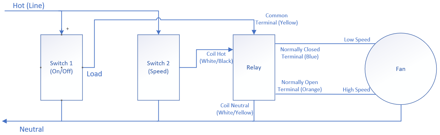
So first switch is master on/off. Second switch is just turning on and off the relay you listed. The relay has a common and a normally open and a normally closed. So when the second switch is OFF the relay will be in the normally closed position which is low speed. If the second switch is on the relay will switch the normally open side on (turning off the other) and be in high speed. This way there is no possibility of powering both at once. Switch 1 will always act as a master. Grounds not shows.
So just to make sure I understand correctly. Both switches are going to get power from the incoming line. The load on the on/off switch will be connected to the common on the relay to control the low speed of the fan. The second switch will be used to initiate the high speed of the fan and connected to the coil of the relay to trip the normally open circuit on the relay. So could I just use two regular on/off smart switches then?
Yes. Otherwise your second switch would become a “dumb” switch (if it didn’t always have power).
Technically it will “power” either low or high. Its the common power supply to the fan.
Yup. Again technically the second switch is just flipping the relay which is diverting power from the first switch to low or high speed
Yes but make sure the master on off is rated for the power of the fan. The low/high technically doesn’t since its just switching the relay but I assume you want them to match.
No, I’ve only used the GE ones also…got like 30 in my house currently. Electric motors are inductive loads so make sure whatever you go with is capable of a inductive load at the amperage the motor needs to start. The ZooZ ZEN21 doesn’t list inductive or motors as supported, the GE 14291 does say it supports up to a 1/2 HP motor. Keep that in mind.
Or you could add another relay that can handle the power load off of switch 1 and make this even more complicated.
Thank you vseven for your diagram. I finally did this project using two Nutone NWS15Z, one as as power switch and the other as a speed switch, connected to a RIB2401B Relay that controls a Quitecool 5400. One thing to note is that the HIGH Speed wire that was in my QC 5400 control panel was colored blue not yellow as stated in the manual. Missing in vseven diagram was the hot line (Black) from power source to QC fan. Please see below for wiring diagram that I used.
Thank you Wilbert_Sison. Your diagram was perfect for me. I hooked up the relay to two gosund smart on/off switches. One for on/off, one for high/low. Without your diagram I was lost. Cheers
Hey vseven i know this is a kinda old thread but ive been trying to do the same thing that op wants to do and a say your diagram and then read/ noticed switch 1 isnt being protected from the amps from the fan. So i came up with this using the RIB2401B relay. Was wondering if you or someone else could verify i have this correct. Both switches protected, switch 1 on/off and switch 2 controlling the speed. And at the end of the day everything fuctions properly. Thanks
Again I’ll state I’m not a electrician by trade but what you have looks correct to me. Switch 1 energizes your first relay which then supplies voltage to the second relay. Just need to make sure the relays you are using are rated for the load. The RIB2401B are good for up to a 1hp motor. (The default GE switches are good up to 1/2hp motor)
Ya i totally get your not liable i just wanted another set of eyes to verify that what came up with made sense to someone else. I looked at it for awhile then started to second guess myself.
I’m in the process of having to replace my relay because it doesn’t seem to be sending enough power through to my unit any more on start. I’m looking over your wiring diagram and it’s confusing me, likely because I’m not great at reading them. But I don’t get the two pictures of the relay. Also are you wiring the load of both switches to the 120v on the relay? Sorry guess I’m just not understanding it, but would love some idea of how to wire my new one, because I have had to replace switches and now it seems like a relay for the way I currently have it hooked up.