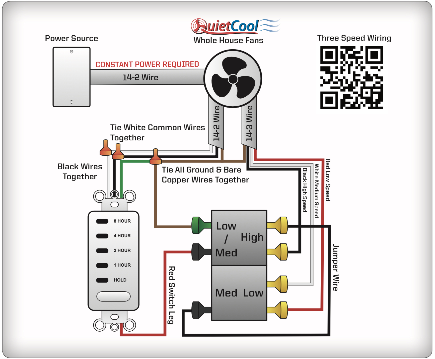
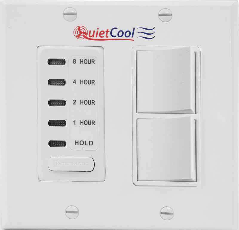
Hi, I am looking to install two QuietCool three speed whole house fans. They are super quiet and energy efficient but their timer and speed switch setup leaves some things to be desired. The fan has a constant power source but the 120v hot leg is then wired to a push button 8 hour timer that feeds a dual switch setup to select low, medium or high speed. The two speed switches are chained together so the output to the fan is over 3 hot wires, one for each speed. I was trying to thing of a way to replace this setup with something that could work with ST. Any thoughts on how I could have a device that could power only one of three power legs at a time? Thanks
I suggest for simplicity, just pick a single auto-speed, and you add relays, that energize the single-auto-speed, and disconnect the manual speeds. More automatic speeds will require more relays.
There are usually three different ways to do this.
- pick one speed and then automate turning the fan on and off
This is probably been the most popular over the years. It’s pretty straightforward. You add a smart on/off switch (not a Ceiling fan control switch and not a dimmer switch) And then you just turn it on and off. You do have to check the specifications to make sure he can handle the current draw, but this usually works pretty well if you’re OK with just having one speed. There are a number of threads in the forum about these projects.
-
choose a fan which has its own app, run it on an android phone, and use a combination of Tasker and sharptools to integrate it. The app doesn’t have to have any other integrations, not even Alexa, it just asked to have an app on an android phone so Tasker can interact with the app. I have an actually heard of anyone doing this for a whole house fan, but it’s been done for a lot of other appliances, and it should work. @joshua_lyon might Have more thoughts on this.
-
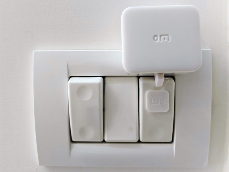
add robot button pushers to the physical wall control, and then automate those. This actually works fine, We use it at my house, people have used it to Retcon air conditioners, DVD players, coffee makers. The button is substituting for the human finger rather than trying to do anything with the wiring or electrical flow. This is quite simple, but can get expensive, as you need a different pusher for each button And those cost about $30 each, plus $40 one time for the button hub. Switchbot has an integration with The new V3 smartthings app which works quite well. Again, I’m using it at my house.
So this may be a more expensive solution, And it may look weird on the wall, But you can probably replicate all of the existing functionality of the wall controller. Because you’re just replacing the human finger that would push those buttons. So this could definitely give you speed control. And it doesn’t violate the warranty of the fan But you can probably replicate all of the existing functionality of the wall controller. Because you’re just replacing the human finger that would push those buttons. So this could definitely give you speed control. And it doesn’t violate the warranty of the fan. 
See the following thread for detail discussion:
2020 Switchbot Review ( robot button pusher), integration through IFTTT or new V3 app
- One other possible solution would be to find a whole house fan that works with Amazon echo and then use alexa routines (not SmartThings routines) as an intermediary. A quick Google search turned up a couple of these being implemented by professional installers, but no off-the-shelf products. In the future we may see more of these, I’m just not aware of any right now.
So there are some possibilities depending on exactly what you want to do and how much you want to spend, but nothing really easy or designed for this purpose.
Thanks for the ideas. I appreciate the suggestions on looking at other fans that have an app but I have not found any whole house fan that has the performance and energy efficiency of the QuietCool line. I live in the SF Bay area and our power rates are crazy high and I need something to keep the utility bills low. So I want to stick with QuietCool even if it means I do not have it tied into ST.
I am still doing some research and have an idea that is not fully researched yet but wanted to get your thoughts if it was even possible. I was thinking of using a z-wave switch/relay to control on/off of the fan, which would replace the timer in the drawing above. Then I would use a FortrezZ or Enerwave dual relay z-wave module and I would then wire two normal SPDT relays, one of of each relay control from the relay. I can use this to replace the two speed switches in the drawing above and I would write the SPDT relays up exactly like the drawing. That is all straight forward and easy enough for me to build. The challenge would be in ST or ST via Alexa (which most of the family uses) the interface to adjust the speed would be clunky at best.
Here is where I am looking for some advice. I have played around with ST virtual switches but they seem to only support on/off. It looks like someone wrote a device handler for a virtual dimmer. Would I be able to setup a virtual dimmer so that if I set the dimmer to off it would turn off first switch/relay thus making the fan turn off. Then if I set the dimmer to anywhere from 1% - 33% it would turn the switch/relay on and the set the relay 1 in the dual relay to low/medium (see drawing above) and relay 2 to low. If I set the virtual dimmer to 34%-66% it would set relay 1 to low/medium and relay 2 to medium and if I set the virtual dimmer to 67%-100% it would set relay 1 to high.
With a setup like this using relay SPDT relays there is no way I could fry my fan as I could only ever have one power output on. The hardware side of this is easy for me but its the software side where I am going to struggle. I am not a programmer but just a decent code tweaker/hacker at best. Does anyone have any thoughts on trying to setup a virtual dimmer to function like this? Thanks!
I wonder what the voltages are on the two switches and the Red Switch Leg… Don’t know if they are just signal carriers but why would you need 14 gauge wire for carrying signal…Makes me wonder if you can control the speed of the fan via a Smart Fan Controller…Need a little more information on how it all works. I would pull out a volt meter and see what’s really going on with the voltages.
RonTalley it has to be line voltage as the timer looks to be just a regular wall timer and it needs 120v itself to run. Also the wiring picture I posted above from the manual has another picture (I’ll post it later when I am back online) of the wiring at the fan jbox and it shows connecting the hot to the fan and the black hot wire facing the timer. My guess is the switches directly power the motor but the fan also has some sort of other smarts that need constant 120v. I am going to pickup one of the fans early next week to start working on this as my existing whole house fan is on its last legs. Thanks
The physics for multiple winding devices are really really different from the physics for a lot of other devices. Just really different. You should be fine if you just have an on off switch that can handle the load, but the kind of stuff you’re talking about would really concern me from a fire safety standpoint. There’s a very real risk of literally burning out the fan. Or the relays.
The models you are looking at Are ECM fans, right? If so, one of the problems with the design you’re talking about is that you would be jumping from one Speed to another which just isn’t how those motors work. It would be like shifting gears on a car without putting it into neutral first.
My suggestion is that you get in touch with the company and tell them that you want to add a switch you can control with Alexa and see what they tell you. Because if you can control it with Alexa, you can probably use the same device to control it from smartthings.
But you’re thinking about it like three different motors, and that’s just not what it is. It’s different gear speeds with the shifts between them managed electronically And that’s just tricky.
Taking an on /off switch and putting it upstream of everything else and just providing current or not is almost always OK. That’s pretty much the same thing as throwing the circuit breaker. But that’s why people who choose that method just pick one permanent speed. They let the existing ECM electronics handle all of the surge and adjustment issues.
But again, just talk to the manufacturer, I’m sure that’s a question they get all the time.
JDRoberts if you look at the picture from the first post that is directly from the manufactures install guide and those are the “speed” switches they ship with the fan. My whole goal is to replicate those exact switch configuration with two SPDT relays tied to a dual relay z-wave module and then an on/off switch to replace the timer they provide. I get your concerns if I was trying to use a real dimmer or something to control the speed differently than the manufacture recommends but I am not. I just want to build a z-wave controllable replacement and then use a virtual dimmer switch in SmartThings to control which of the relays/switches is on or off at any given time. Does that make more sense? Thanks for the feedback!
This is likely the ECM Control. It just doesn’t work as three separate branches as you’re envisioning it’s more complicated than that.
What you’re suggesting is cutting power to one leg and restoring it to another in order to activate the different speeds, and I’m just saying that’s like shifting gears without engaging neutral. It’s just not the way these motors are designed.
But again, I suggest you talk to the manufacturer. I’m definitely not a wiring expert, I just know enough to know when to call in an electrician. ![]()
JDRoberts, While I am not an electrician by trade I have done a ton of electrical work for 30+ years across single phase 120/240v systems all the way up to 3 phase 480v systems. I have also installed 3 of these fans for friends and family and the wiring is that simple and does act as 3 separate branches at least back into the fan j-box. I have not dissected one of them to see if that feeds some sort of controller or if its wired directly into the motor. Attached is the full wiring diagram of both the switches which I posted before and also the junction box on the fan itself. As you can see in figure G, the incoming black hot is wired directly into the fan via the j-box and to the timer where it then feeds the speed control switches via the red wire in figure F. Thanks

Like I said, all I know is enough to bring in an electrician. As a network engineer I had to take some courses on the physics of the different kinds of motor controls, but I would certainly defer to any of the electricians in the community, and there are several.
I do think you can ask the company about a switch that would work with alexa with this fan and see what they say about that. It could give you some clues as to a direction for smartthings integration.
JDRoberts, that’s funny I am a network engineer by trade as well or at least I used to be before I went into various corporate roles that are only partially technical. I got my original ccie back in 98 but it’s been a decade plus since I have been behind a keyboard on a regular basis.
I’ll call the vendor again tomorrow but when I talked with them last the only thing they offered was a wireless setup and from talking to one of their distributors they said that while they loved the fan, the wireless option was garbage. I’ll post what I find out. Thanks
Ok I have the hardware worked out. Waiting on a large junction box to install it all. I went with the ZooZ S2 multi relay. It’s a 3 channel dry contact relay. Port 3 is rated for 240v 20amp so I’ll use that to directly the timer in QuietCool’s drawing above. The other two ports are rated at 240v 15 amp which is more than enough for the fan but they are only NO contacts on them. So I am going to wire those two ports over to a pair of SPDT relays. I found them on amazon soldered to a board with screw down terminals for like $7 so it was worth the time savings to go that path.
So recap: power will be controlled via relay 3. It will then feed into the SPDT relay wired to port 1 which will replaced the first speed switch in QuietCools drawing. NO contact will power high, NC will feed the input of the 2nd SPDT relay. It’s NO contact will feed the medium speed and the NC contact will feed the slow speed power. This way it’s electronically identical to the factory provided timer and speed switches and there is no way outside of one of the SPDT relays frying badly that I could power two of the inputs at the same time. While there is a risk for that it’s not much higher than the factory wall switch doing the same thing.
Next step is to work on the software side of things. My “Goal” is to build a virtual dimmer to control all of this.
If I set the dimmer to 0%/Off it turns relay 3 off
If I set the dimmer between 1%-33% it turns on relay 1, 2 & 3
If I set the dimmer between 34%-66% it turns on relay 2 & 3
Finally if I set the dimmer to 67%-100% it turns on relay 1.
It seems fairly straight forward but as I mentioned earlier I am a hack at best when it comes to programming so I am sure I’ll have plenty of questions when I get there. Thanks


How did this work out? It seems very complicated but I can’t find any good alternative. Basically we need a smart switch that has three mutually exclusive positions feeding three distinct load options. I’m using the Lutron Caseta system for my lighting and would love to find something simple - whether it integrates or not.
I highly doubt you are going to find something since you need a switch that feeds the 3 loads but cannot feed more than one at a time. That is why I ended up going down this route. So far its been working great for over a year on two fans (one into the lower attic and one into the upper attic). What I have not had time to do is mess with creating a virtual switch so it shows up in Smartthings as a single device. Right now I have the relay that controls on and off named “Upstairs house fan” or “downstairs house fan” and we just use alexa to turn it on or off since ST is integrated to Alexa. I also have those two relays set to auto turn off every day at 5am so it off before there is any chance of things warming out outside. To control speed I manually go into the ST app to change it but 95% of the time we just leave both on low as its plenty of airflow except on the hottest of days. If you have any other questions let me know.
I’m not real sure if this is what you have in mind, but since this topic popped up, I’ll offer an idea that I haven’t pursued yet.
What I’m thinking anyway is that with a regular “smart switch” i.e. SPST and one of the newer SPDT 2-channel smart relay options, this could be a two device solution.
Here’s the diagram that got me to thinking about it.

The SPDT being basically any smart switch, and the SPDTs being the 2-channel smart relay.
I sometimes get brain block with relay wiring, but unless I’ve just totally missed something, I think it’s viable.
edit: the only thing that stands out , is that diagram doesn’t reflect smart switch wiring and the relay would require it’s own seperate DC power to keep the board online, but the AC wiring betwenn switch and relays would remain essentially the same.
James, what 2 channel SPDT switch are you looking at. I ended up going with the Zooz 3 channel one (Zooz Z-Wave Plus S2 MultiRelay ZEN16 with 3 Dry Contact Relays (20A, 1 - The Smartest House ) which works great. It shows up as a single device with 3 child devices under it for reach relay. The problem is all 3 channels are SPDT. That works for channel 1 which is the “on/off” switch for the fan. For channels 2 & 3 to control the speed you need SPDT like you mentioned. For that I picked up a board that includes two SPDT relays. https://www.amazon.com/gp/product/B00LW15F42/ref=ppx_yo_dt_b_search_asin_title?ie=UTF8&psc=1 $7 for two of them. To power the Zooz zen16 I bought a small board mount 12 volt transformer. This powers the Zooz and the relays. https://www.amazon.com/gp/product/B07FNJZ1PR/ref=ppx_yo_dt_b_search_asin_title?ie=UTF8&psc=1 This overall was the simplest way I could figure out to build this setup.
Oh, yeah… I’ve been goin’ on about the MHCOZY Zigbee two-channel relay in other threads, as it solved some problems for me, especially with its interlock mode.
I’m thinking that some of the others like “curtain modules” etc, could be a nice option too, especially with the ability to wire momentary wall switches etc… Although, I know those can befuddle people, including myself.
Anyway, there are some decent explanations of the MHCOZY in the Amazon images, and there is also a 4-channel available.
Also, it works with the current ST Zigbee Multi Switch DTH, so I’m guessing it will continue with the Edge drivers.
Aliexpress has some other offerings, for the same relay, including a relay enclosure and an RF remote.
edit: And, yeah, the Zooz was also part of my thinking with the previous wiring diagram, I guess it has the momentary switch options too? I haven’t experimented with one.
** So, it might come down to changing the wiring with yours, or I’m missing something important here. I’ll think on this some more, especially regarding the Zen16, and see if I can manage some confidence with my logic.
Ok, I think I see what you mean with the Zen16, in that the single pole is static/fixed to all three relays. I think that is often the case with the curtain modules, as well.
I’d almost call the MHCOZY relay perfect if it had terminals for connecting external momentary switches, although, those could be added with a bit of soldering to the back of the individual relay buttons.
What you have seems to be doing essentially the same thing as the diagram would do with the Zigbee relay. And if it works, why fix it…
*If I get my hands on a three speed device, I’ll try to confirm if what I earlier proposed, does in fact work.