I’m just getting started with smart home stuff and I wanted to take on something more complicated than pairing a few light bulbs: I want to add a fan controller for the overhead fan in our living room.
Now, I’ve read the other topics about the GE Smart Fan Control, and that looks like what I need. (I haven’t bought anything yet, so if I’m wrong, please say so.) I took the switch plate off this afternoon and was presented with what seems like a crazy wiring setup that doesn’t match anything else I’ve found. And bonus, the idiot builders who built our house managed to spray drywall over everything in the box, which makes it even harder to figure out what’s what.
So, it’s a 3-gang switch. The left switch is a 3-way switch to the kitchen light, the middle one is the fan, and the right one is the light fixture in the fan. But the switches seem to be wired to each other? I’m lost as to what that’s doing.
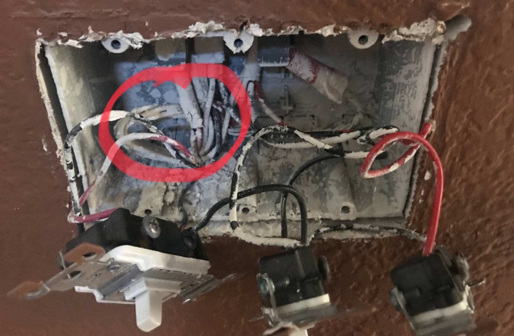
Here’s the best picture I could get of what’s going on here:
And I drew a picture as best as I could of what wires are going where:
[Only one image at a time apparently…]
So, I’m assuming the top wire on each switch is load and the bottom one is line and that capped wire is where I’d connect the neutral? Is there a way to verify this? I have a pen voltage tester. Is there a safe way to test this?
Sorry, I’m probably asking too many questions at once. It’s just of course the next thing I wanted to tackle here would be the most complicated and messy switch in the whole house.
If anyone could provide any insight as to what I need to do here, I would be very appreciative. Thanks,
That’s just jumping the line (hot) from one switch to the next.
You’re likely in a good place here as you already have separate switches to the fan motor and light. Meter the lines to be sure what is what but you should just be able to remove the middle switch and put in a smart Fan Control. The black wire that is jumped across switches will go to the Fan Control’s line. You’ll add a neutral by pig-tailing to the white bundle (I believe I can see that although the wire nut for it looks like it’s tucked out of sight).
No. That is the ground bundle. You will also add a pigtail to that for your new Fan Control switch’s ground terminal.
There appears to be a white wire neutral bundle, see circled below. Is there a wire nut tucked behind those wires? Is so you have all you need to hook up the smart switches.
This is perfect, guys. Thank you! I don’t think I realized there was another bundle back there since it blended into the background.
One other random question: if the one obscured is neutral and the one at right is ground, how do you tell which is which? Is it just the wire color in this case? This is more to satisfy my own curiosity because I’m not sure what I should be looking for.
Bare copper wire should always ground. That is about all you should ever take for granted. Every other wire in junction box could be Hot or Neutral. Never assume based on wire colors. Always confirm with a volt meter.
Also, if in doubt, hire an electrician. Someone, somewhere, needs you in their life! Safety has to be everyone’s number 1 priority when dealing with mains-level voltages (110VAC / 220VAC.)
While that’s true, if a bundle only has white wires, the likelihood is 95% that it’s neutrals. A bundle containing both a white and a colored (red or black) wire is almost certainly a switch leg or travellers for a 3way switch. Colored (red/black) tied together can be constant power or a switch leg or travellers for 3way switch. Provided, of course, an actual licensed electrician did the wiring. If it was a homeowner, all bets are off.