Before I begin, please note that I’ve wired many of these throughout my home and even for others. While I’m not an electrician and I know a common answer will be “Call an electrician,” I’m well aware of the dangers but also am really perplexed since I’ve done so many of these and haven’t seen this issue in my house or others before.
With that said, here’s my dilemma. I went to wire up my hallway light using a GE Zwave and Add-on switch (again, I’ve done many before). Following their instruction and video, I find which switch is the ‘master’ by shutting off the power, removing the switches, turning the power back on and then touching the leads with a multimeter, looking for voltage.
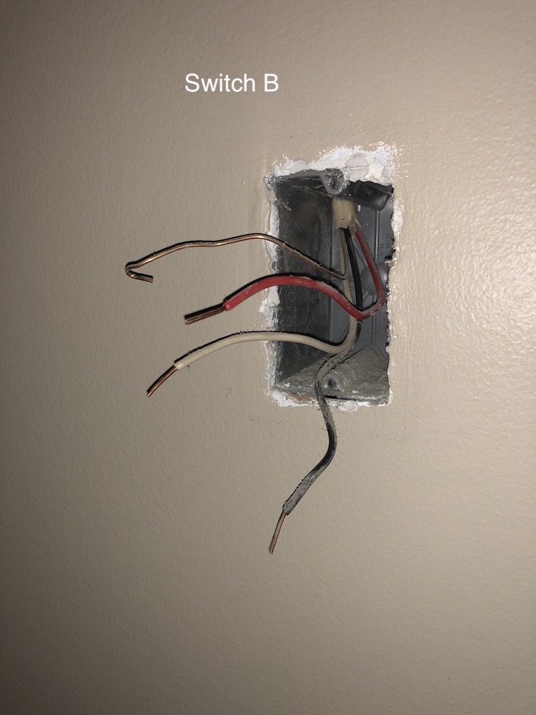
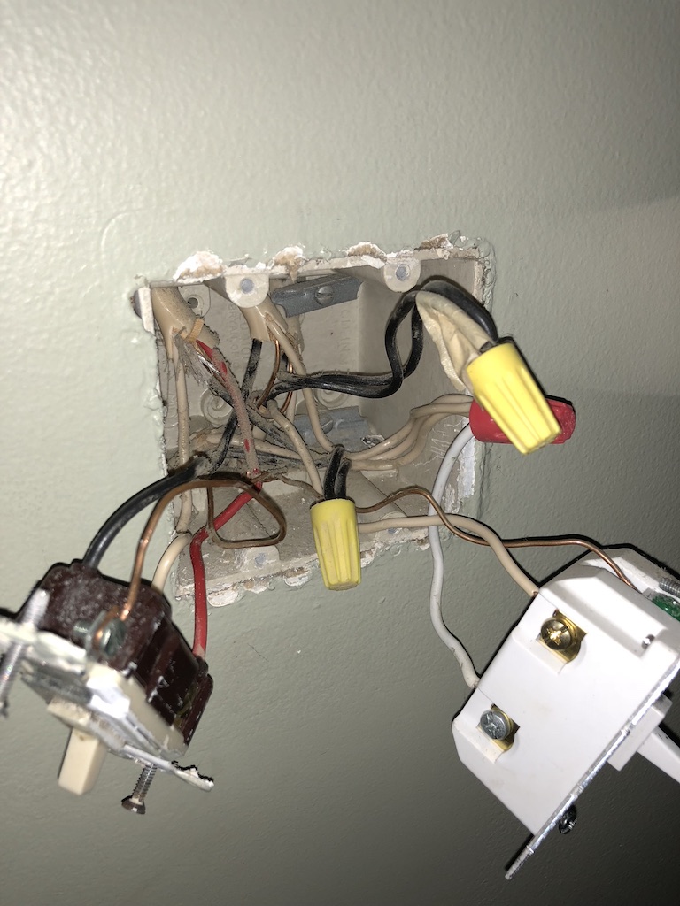
Well, here are the two outlets. We will call the dual gang 'Switch A" and the single gang ‘Switch B’
(Note we are only looking at the wires. The other switch you see is for a different light)
So when I turn the power on and touch the leads looking for continuity and voltage…I get nothing. I then take my non-contact sensor and go to Switch A…nothing. I take it to switch B and the black wire shows voltage! So I was like cool! That’s the master…except there is no neutral.
Switch A has a bundle of neutrals in the box and oddly enough, the other switch in the same gang is also the add-on, not the master. Therefore, I am completely confused as to how to successfully connect these switches to this circuit…
To summarize:
I get no voltage from either Switch A or B when the power is turned on, with the switch disconnected using a multimeter.
Switch B, black wire is full-lights/beeps when I use my non contact sensor, but it doesn’t appear to havre a neutral.
No other outlet is wired like this at my house so I’m not sure how the dumb switches are working as a perfect 3 way yet I don’t seem to have power going to either switch??
Any guidance is appreciated. I’m really hoping I can solve this one because it’s one of the only lights I don’t have as controllable and is the one that always seems to be left on, lol!
Based on the picture it looks the the black wire on switch A comes from another wire, I can’t tell for sure. Does the black wire come from the same wire as the red and white? It looks the the black wire in Switch A goes to a wire nut. Where does that black wire come from?
Yes, and it looks as if the white wire from that same Romex is hooked up to a black wire with a nut on the bottom of the box. You might have power coming to the light first. Did you label which wires were hooked up to the common screw on your old switches. That is important to trace where whose come from.
Is the other switch in the dual gang on the same circuit?
Yes, both the 3-way I’m trying to complete and the GE Switch already installed are on the same breaker.
The white and black wires from switch A are coming from different Romex. I can check in regards to the common and report back. I was able to reconnect the old switches back up and put everything back to normal.
Both dumb switches are wired where the black wire goes to common, the red and white wire are on the other two terminals at the other end of the switch.
Ok there is your key. Given only 1 14-3 Romex in Switch B we know the Aux switch will go there. We will just need to get neutral to this box via Switch A.
In Switch A, trace the black common wire to see which Romex it goes to, that is likely your load to the fixture. Once you figure out which Romex that is, what is the white wire hooked up to in that same Romex?
If the black common wire is indeed a different Romex, trace the white and red wires hooked up to the switch and figure out what the black wire is hooked up.
Once you have all of this post back here with your findings. A clearer picture with all your wires separated will help too.
Sorry I wasn’t able to get the picture last night - worked late and by time I could do anything regarding the switch, the little one was already sleeping (her room is on the same circuit and I wasn’t risking shutting off her sound machine or the hue light turning on when flipped back!).
@ritchierich Alright, I’m back with the info! Sorry for the delay…the only times I’ve been free to do this have been at night and with the little one sleeping, that wasn’t going to work. A weekend can’t stop me though!
Below are the pictures requested. I also traced all the lines and drew up (chicken scratch) a wiring diagram. I’m going to make it a bit neater, digitally, and post that up as it may be easier to see where everything is going versus the pics. However, here are the pictures of the boxes. Any help is very much appreciated!
@ritchierich Here is a quick wiring diagram I made. One note: There is one other romex that hits the box (looking at the picture, dual box, top right most romex). However, this was not connected to any of the switches or lines for the switches, so I didn’t add it to the diagram. The diagram shows all of the switch wire connections.
Orange circles are wire nuts, dual yellow lines represent the romex trunk. All other colors are respective to the color wire connected to the switch.
To summarize, I’m looking to swap the ‘reg switch’ on the left with another ge smart switch + add on for the 3-way. However when I test the lines, the single gang box switch appears to have the ‘hot’ not the reg switch in the dual gang box.
Ok marked up one of your pictures to help. Your line and load are all in the 2 gang box and line is being “sent” to your single gang box via black wire circled. For 3ways to work, line is on 1 switch and load is on the other.
The one going to the 14-3 Romex in the upper left side is not needed. Put a wire nut on it. This is the wire that is feeding power to your other switch which we don’t need any longer.
The one that is part of a 14-2 Romex is your line and hook that up to line on your master switch. Looks like only 2 wires are bundled together if more then hook both up to master line terminal.
hook up black circled load wire to load on master
Neutral:
put pigtail into neutral bundle or you could pigtail off other smart switch in second hole.
also hook up white wire from upper left 14-3 Romex that is currently hooked up to your switch into second hole in neutral terminal. This will send neutral to your aux switch.
hook up red from upper left 14-3 Romex to traveler
Thank you for the detailed walk through! I will give this a shot and report back. I have to ask though, how in the world are you able to give such detailed info just by looking at 2/3rds of the circuit (no pic of the fixture wiring)?! Were you/are you an electrician?? Either way, I’m impressed! Thank you!
I am not just very experienced with my own house and friends houses. It’s a fun puzzle for me. I can thank a former neighbor of mine for teaching me a lot of the basics as he owned a commercial electrical company.
@ritchierich You sir, are the man! Just got finished wiring them up. Both switches work, it’s currently paired to Smartthings, and I now have Alexa control. Thank you!!
@ritchierich
Interesting solution. There are a lot of inquiries here where a neutral is lacking. Just so I understand the concept, I take it that the remote doesn’t need both travelers as the signaling is done over on of them?
So you steal one of the two travelers and use it to send the neutral?
Correct, at least for the GE Aux switches. They only require traveler and neutral, so in a situation where load and line are in the master switch location the third wire isn’t needed. If load was in the Aux location the black wire could have been used for it.