Thank you so much. I was struggling with this till I came around to this picture. Now if I think about it, it makes intuitive sense. Thank you again.
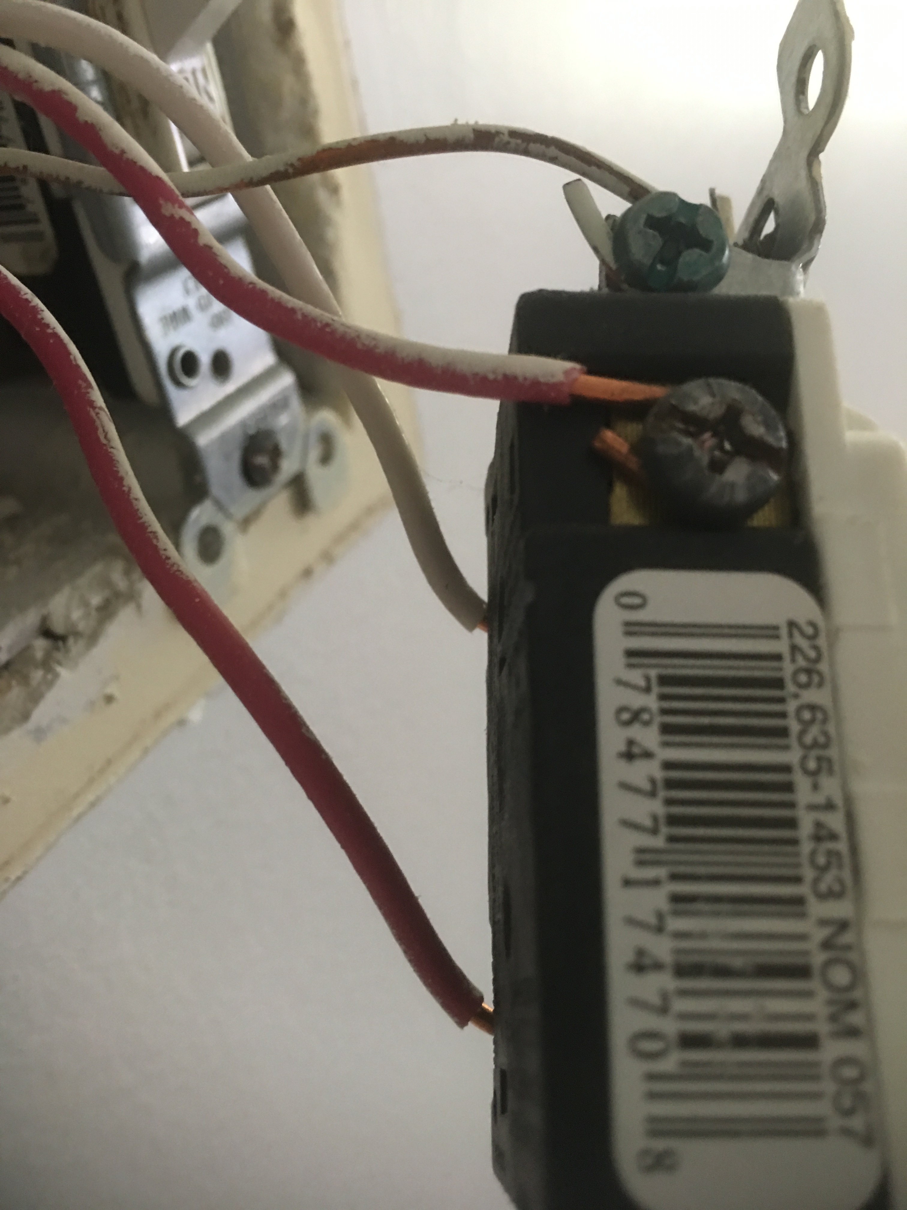
I am needing help wiring a 4 way. I have wired a single zwave switch but not a 3 way or 4 way. Here are pics of the 3 light switches in the 4 way.
The first picture has two reds on one side and two blacks on the other side.

The second picture 3 blacks on one side and one red on the other side.

The third picture has a black and a white wire on one side and a red on the other.

Anybody out there that can help me out?
Not possible to help just with pics. You need the test the cables using voltmeter to determine hot, load, neutrals, and travelers. First isolate the hot, then everything becomes easier since you can use the hot to discover where each traveler is going to (tripping them at the hot location then testing other cables to see which now has voltage) and which wire is the load (usually by tripping hot and what you think is load and seeing the light on) . When I wired 4-way the load and hot were not at the same box so I had to use traveler with nut only (no switch wiring) to transfer hot from an aux switch box to maser switch box.
Thanks for replying. I’m not a electrican but I have connected and replaced light switches. I have also connect just the single pole zwave switches but not a 3 way or 4 way. I understand I have a master switch and 2 slaves z wave switches. Now I’m trying to figure out the wiring of the mysterious 4 way. Only thing I find odd in my setup is that a neutral wire is connected to the common screw. Is this normal? …to determine the hot should I remove all 3 switches and leave the wires sticking out and then use a voltage detector to determine the hot? Thanks
Just a guess but I think the white wire at your common screw is most likely your line hot connecting to the line bundle at the 4 ways switch box. If no one stepping in. I could assist tomorrow.
It’s unusual to see neutral connected to a dumb light switch. As @Navat604 is suggesting it could be used for something else.
That would be greatly appreciated
It’s going to be difficult to find line hot with a voltage detector. There are way too many wires and any wire close to the line hot will also cause false positive. You will need a volt meter and 90% of the time.
I see other light circuit on the first and second pics. Turn off the breaker to the light and confirm if they are all using the same breaker. This wil make it easier to check line and neutral.
The line hot will be on the common terminal of one of the 3 ways switch. The 4 ways switch is usually just for travelers so the line will be on one of the 3 ways and the load will be on the opposite 3 ways.
You just need to disconnect the wires on the common screw terminals of both 3 ways switches and place one of the meter probe on the ground wire if you are not sure about neutral.
Ok got a spark so now I’m done. Thanks for helping, going to hire an electrican. I found another dumb switch with the neutral white wire on the common. Im afraid to burn out my switches.
1 Like
Edit: Disreguard
Hello, hopefully someone will be able to help me out with this and my limited experience. I am trying to wire up my GE Smart Switch 14292 and Add-on Switches 12728 to my existing basement two fixture lights. I just don’t want to fry any of the switches.
Box 1 - Black is line and reads 120v. This is the only 3 wires coming out to the switch. There are others but they are for an outside receptacle and light.

Box 2
Box 3

I went ahead and pulled the fixtures to show as well.
Fixture 1

Fixture 2

I have tried skimming through a few threads but I’m just not seeing my setup. Then again my head starts to spin a bit after so much…lol Thanks!!
the wires in your fixture are so you can have a fan and light controlled separately. the only one you need to worry about is the red, its being used as your hot wire to load. take a voltage meter or sensor and figure out which of the two red wires attached to your switch has voltage when the switch is off, this is your line (hot) the white is your neutral, the one that has no voltage at all is your load.
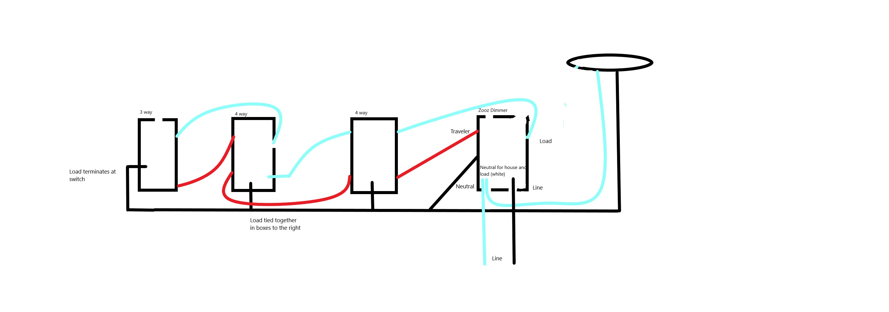
Well, I realize I’m reviving a very old thread here, but believe it or not it’s the newest of these threads. I’m hoping that someone could help me understand what I have going on. My Line and Load are in the same box. I tried to order add-on GE switches however I have two 4 way dumb switches in the mix. I’m going to apologize for my diagram up front. My personal computer doesn’t have the same drawing tools. Oh white is light blue for obvious reasons.
None the less, the add-on switches have two terminals so I’m assuming that I’ll be putting the two travelers (red) into the traveler post on the add-on switches and pigtailing the white. How do I terminate to a two post with the common, traveler and load?
It’s a weird setup and I haven’t seen a diagram like mine anywhere. I’m hoping someone has some knowledge on here. I had originally gone with the Zooz Dimmer that doesn’t require you swap out the dumb switches but I’m on my second one and now the lights won’t turn off or respond to commands.
Hey team, this seems to be the 4-way Jasco thread lol. I apologize for reviving, but I don’t understand how to wire my switches. My wiring is like this:
Box 1 has 14/2 with line and a 14/3 that goes to Box 2.
Box 2 has the 14/3 from Box 1 and another 14/3 to Box 3.
Box 3 has the 14/3 from Box 2 and 14/2 to load.
Everything shares a neutral (is my assumption since all my neutrals are tied together).
First I tried this configuration:
- Master dimmer in Box 1
- Add-on switch in Box 2 with both traveller lines in switch and blacks tied together
- Add-on switch in Box 3 with traveller line in switch and blacks tied together
This configuration yields a closed circuit that makes the dimmer work but not the add-on switches
Then I tried this configuration:
- Add-on switch in Box 1 with traveller in switch and blacks tied together
- Add-on switch in Box 2 with both traveller lines in switch and blacks tied together
- Master switch in Box 3
This yields the same result.
I understand that I’m basically closing the circuit with the blacks and the travelers aren’t being used, but I don’t understand how to fix it lol… Any suggestions would be very helpful.
What do you mean by this? Aux switches require neutral along with traveler wire. Did you hook up both red to traveler terminal and white to neutral terminal on both Aux switches?
Late to this party but running into same issues as all above. Here’s what I have:
Current layout with regular toggle switches.
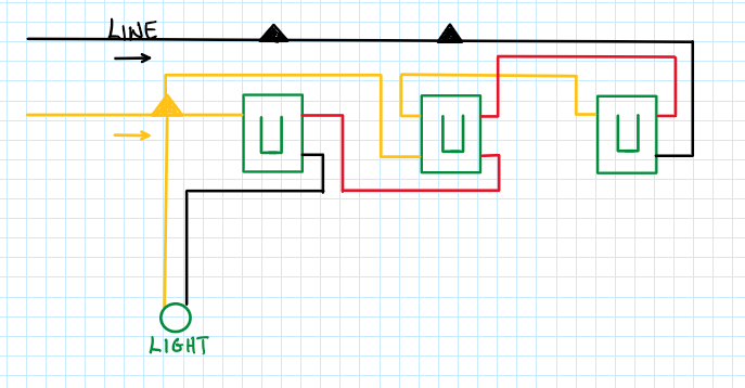
I believe the smart switch layout should be

But it’s not working…… thoughts? I know my line in (hot) is correct.
I have multiple 4 way and 5 ways installations.
One key question: does your main switch location work?
If your main switch isn’t working, then focus on that first:
Ensure your line and load configurations are correctly oriented and get that part working.
Once you have the main switch working, then for the additional locations ensure you are using an add-on switch, not a regular Zwave/zigbee switch, and just connect the traveler and neutral wires to the proper points on the switch.