I have dimmable commercial electric LED can lights that have been wired up to a normal 4 way circuit for about a year. I tried replace the switches the other day with the GE Dimmer 12724 and the lights would flicker at 80-100% power. I want to be about to have a bright kitchen at times so I decided I didn’t need the dimmer and installed the GE Smart switch 12722. Now when I turn the lights on they flip on and off and stay off. I really would appreciate some help on this. Wife is getting upset that there are no lights in the kitchen (I don’t blame her). I’ll take pictures or whatever you guys need to help!
If they flip on then off, they may be triggering the overheating circuit on the switch.
Exactly what is the load on the switch?
Also, did you replace each of the three switches with a networked switch? You cannot put just one network switch into a multi way circuit with nonnetworked switches, they don’t get wired the same way and you will have problems.


The Load switch is wired to 14/3 black wire in picture 3. The one I was the most confused about when I was doing it was picture 1 there is only a red, black and white. I nutted the black and white together as seen in the pic. The Master switch “line” comes from a 14/2 that comes into the box. The white wire is nutted with some other black wires that gives the black wire power. Without the white connected the line has no power.
Yes, they are all replaced with the companion switches. What do you mean by load on the switch? The Line power is 120 volts if that’s what you are asking.
Black (hot) to White (Nuetral) isn’t normal. I can’t tell from the pictures but you might ohm out the wires with a meter, label them and then create a schematic to see if you can determine if your wiring is the issue. As @JDRoberts points out, the single smart switche does all the work of supplying power and switch on the circuit. You’ll need the companion switches on the other switches replaced with Aux switches. They don’t carry power like a traditional 4-way, they’re basically a switch contact that when closed signals the primary switch (via the traveler and/or Nuetral ) to turn power to the circuit on or off.
Example: https://www.amazon.com/45610WB-Z-Wave-Add-Auxiliary-Switch/dp/B0080G4OJO
Something else to consider is if you’ve added rules, you could be fighting a rule you may have inadvertently created. Remove all rules or power off the hub to ensure the switch isn’t getting conflicting commands from you and the hub at the same time.
No rules are created yet. I haven’t gotten that far. I agree white is weird. I have been using a multimeter to determine what I can.
“Load on the switch” = The load that the lights will pull when they’re on. So exactly what bulbs do you have on that switch?
If the load got too high, the switch might overheat, which would cause the on/off pattern you saw, but it can also be caused by other wiring issues.
Oh ok. There are 6 lights and pull 10 watts each, so I’m only 60 watts.
If you suspect it’s something with the switch, install it on a 1-way circuit. This will remove the wiring complexity from the equation and let you prove out the switch.
If the switch works on a 1-way configuration, it’s your wiring in the 4-way. The switch may be detecting a short and protecting itself.
Tell the wife the truth. Irespective of the smart switch. You found a wiring problem while swapping out the switches and need to resolve it to prevent burning the house down. That black to white has gotta go.

This is my exact setup.
Picture 3 would represent the 3rd switch which is wired as my master.
Picture 2 is the middle switch.
Picture 1 is the first switch.
Hope this helps you guys help me out. This is literally the EXACT why my wiring is.
@dalec @ritchierich I saw from another post you were able to figure out this sort of setup. Could you please help me?
Black nutted to white in the box tells me that you have the " old short cut" way of wiring where the main line power goes directly to the lights and 1 piece of Romex is run from the light to the switch and back to the light. I would definitely get a test meter and start testing the wires to see exactly what is what and not just assume based on looks and colors)This is " fine" for old dumb switches but will not work with smart switches. If it did I would have a lot more switches and a lot less bulbs.
Every smart switch in my house requires me to get into the walls and rewire everything to the breaker box the " new improved way". That is why I used the Lightify can lights in my kitchen. I didn’t care about the colors, I just didn’t want to have to rewire the kitchen (again). I didn’t even think about rewiring all the light switches when I redid it about 5 years ago to add all the outlets now required ( and used) that weren’t needed the last time it was redone 40-50 years ago.
I have verified that this is the way it is wired because the white ties into box 1. The black from that 14/2 then becomes 120v. I wired the 120v to the line on the main switch. Then I took the 14/3 wire and wired the white to the power, black to the load, and red to the traveler. The main switch is then wired to the neutrals in the box and ground to the ground.
Box 2 is the 4 way. 2 reds to the companion, blacks nutted together, whites nutted together. Companion wired to neutrals and ground to ground.
Box 3 is 14/3 white and black nutted together, companion to neutral and ground to ground and traveler (red).
I don’t get the lights flipping on and off any longer. I just get the master to “click” when activated from any of the switches. I feel like I’m really close, but you say this is not a possible wiring setup with these switches. I hope this is not the case.
This really isn’t your exact setup because you have 6 lights, multiple switches at a box? So how many actually lights switches are you replacing? The GE can slave up to 5 Add-On switches I believe.
If this is indeed your setup we can get it fixed pretty easily. It is always about communication and we need to be clear on what is what.
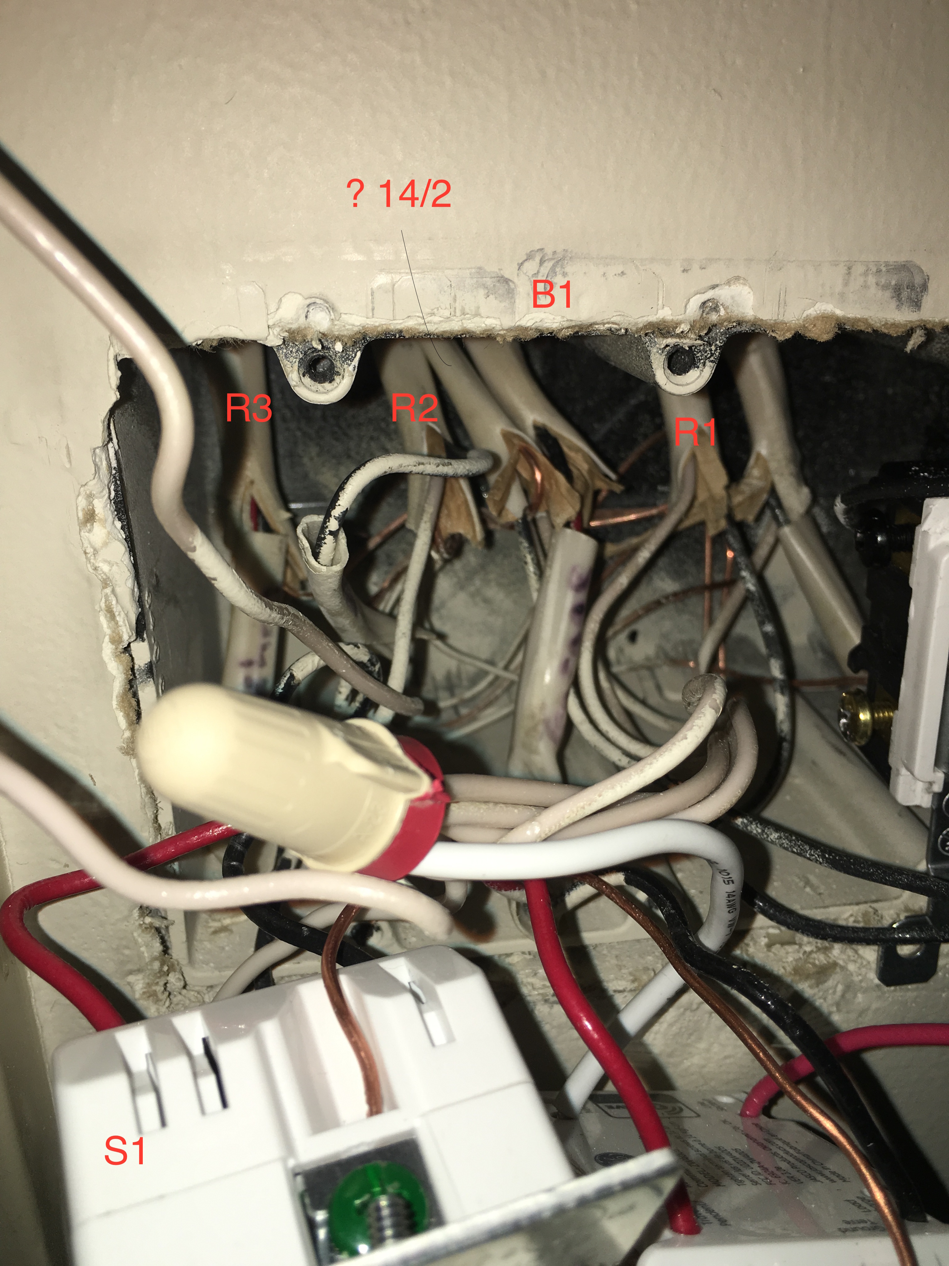
Therefore what I need you to do is confirm each box, switch, and wires in your pictures with the diagram so that I can direct you what to wire where, OK? So for example we need to label each box as B1, B2 B3, B4. Each romex as R1, R2, R3, R4, Each switch as S1, S2, S3. And each light as L1.

So in your photos you have to label every switch, wire, romex that is the EXACT companion from in the diagram. By any chance did you take BEFORE photos of the dumb switches and how the wiring was when it worked? These photos don’t show enough. I need to see each romex and where the wires are terminating to on your switches. Pull out the switches from the boxes so the pictures show us what romex is going to what switch. I can’t even tell for certain which is your 4-way switch because I can’t see the terminations.
In your last post you mention wires and boxes numbers etc but I still can’t tell what devices or wires you are talking about from looking at unlabeled photos. That is why I need lots of detailed pictures to point you in the correct direction. And please label all the dumb switches as well.
I am doing a lot of guessing on your photos but picture 1 is what you call box 1 and is B1 in my diagram? So picture 2 is what you call box 2 and is B2 in my diagram, and picture 3 is what you call box 3 and is B3 in my diagram? Am I close?
As far as the diagram, that is exactly how the switches were wired before. You are close to deciphering what I was trying to communicate. I am replacing 3 switches, so the diagram represents my situation well.

As far as the lights there are 6 lights. That I believe are on R2.


Closer of B1 With a 14/2 that black is nutted with R1 and all the other power and white with the neutrals.
Thanks you are getting some better info! Unfortunately you need to remember I can only see what you are sending me and I can’t tell what is being terminated still to the back of the switches so I can’t tell for certain where the mistake is. And I can’t see exact model numbers of your devices. Don’t hold back buddy and give it all at once to me… 
So why don’t you tell be since I can’t see the Romex and what it is terminated to. For example is your Box 1 terminated exactly as below?
Box1
R1-blk to R3-wht and S1-LINE
R1-wht to R2-wht and S1-NEUTRAL
R1-grd to grd and S1-GROUND
R2-blk to S1-LOAD
R2-wht to R1-wht
R2-grd to grd
R3-blk to (Not Used) cap off
R3-wht to R1-blk
R3-red to S1-TRAVELER (leave disconnected until S1 works correctly)
R3-grd to grd
So let me first verify your hardware. You didn’t tell me what each S1, S2, S3 was. Give me the model numbers exactly. From your OP title I am confused.
Is it GE 12724 Smart Dimmers or GE 12722 On/Off Switches using the GE12723 Add-On Switches?
I believe I know your issue…
In your S2 box, you have two black wires bundled together from R3 and R4 that shouldn’t be. You don’t need the black wire from either of these bundles so unbundle them and put individual wire caps on them.
In your S3 box you have a white wire and black wire bundled together that shouldn’t be. The white wire in that bundle is the neutral for your S3 switch, so remove the jumper you have currently as your neutral and replace it with this white wire. Wire cap the black wire from this bundle as you don’t need it.
I believe these two issues is causing 120 to go to your Aux and causing the issues. The aux switches only need the red traveler and a neutral. The previously used black wires are not needed and need to be individually wire capped.
B I N G O ! ! @ritchierich wins the puzzle decipher ![]()
That is the R4 black that is the spare, just cap it. It is OK to leave the white jumper though. It doesn’t hurt to leave it in and since it is stranded it is easier to work with in getting the switch back in.
UPDATE: @ritchierich Ageed, I didn’t see it was from a different neutral. ![]()
It’s better to have the neutral on the same circuit. Plus less wires to shove into the box. 
Per specs, the GE 12724 can handle 4 add-on switches, not five. A total of five switches in a six way set up, but one of those five is the master. ![]()
https://byjasco.com/products/ge-z-wave-wall-smart-dimmer
Also, you probably already know this, but the GE wiring for these switches requires that they all use the same neutral.