I recently had a GE 12722 Z-Wave switch die. It died in the same way many others have reported (it wouldn’t turn on, even manually). So I replaced it and decided to take it apart instead of trashing it. Here’s some pictures! Let me know if there’s anything you want a better photo of. I don’t see any obvious signs of failure on the circuit boards.

2 Likes
I just had one fail also. took it apart, first 2 screws are a pain, and also could find no obvious problems. If anyone comes up with a solution I would be interested.
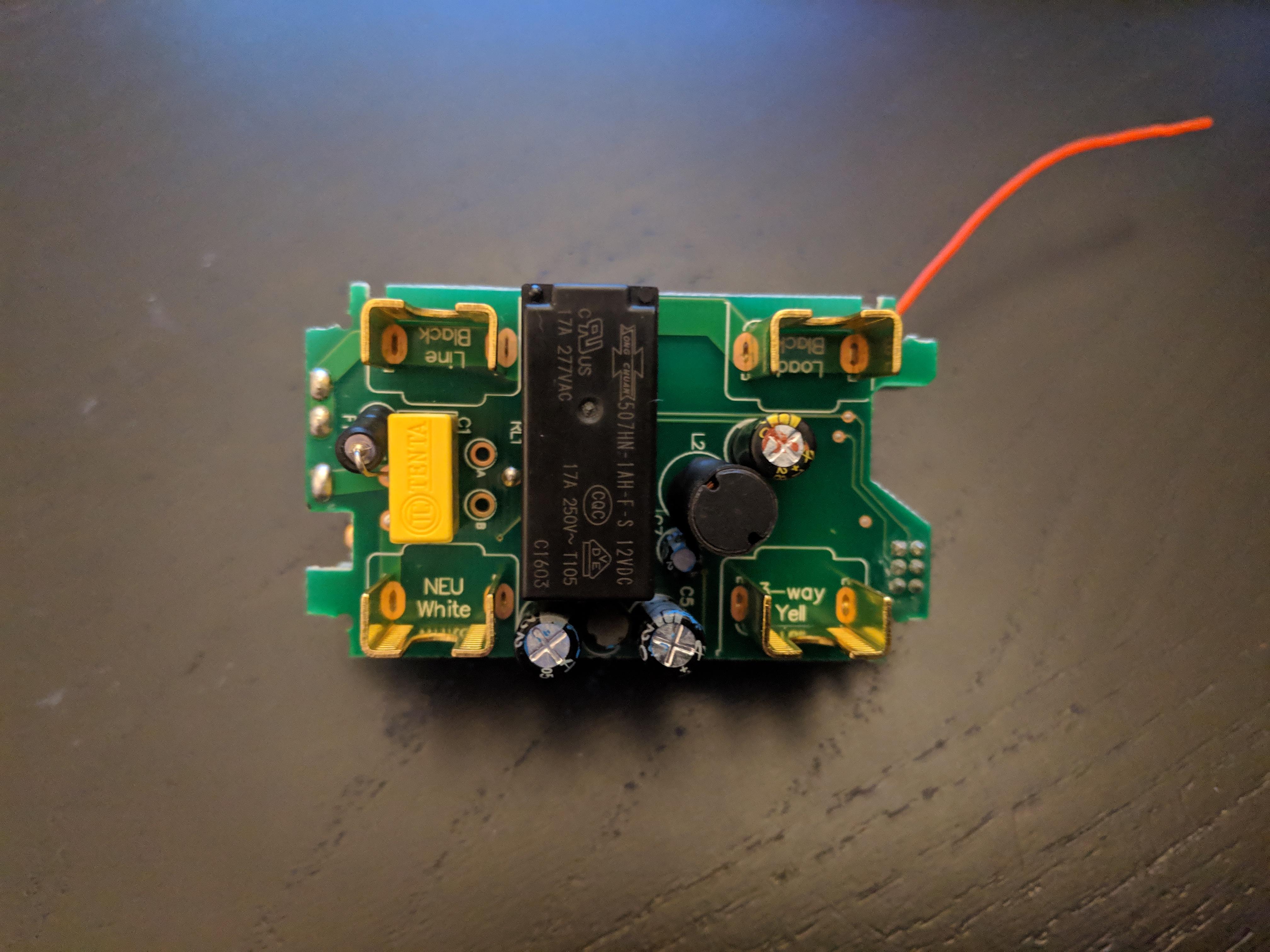
I suspect the relay is broken. 507HN-1AH-F-S - You can buy one online and replace the old relay, you will need a solder.
Would you want to try replacing the relay? https://www.bonanza.com/listings/888N-1AH-F-S-12VDC-Relay-Song-Chuan-Brand-New-/445157422
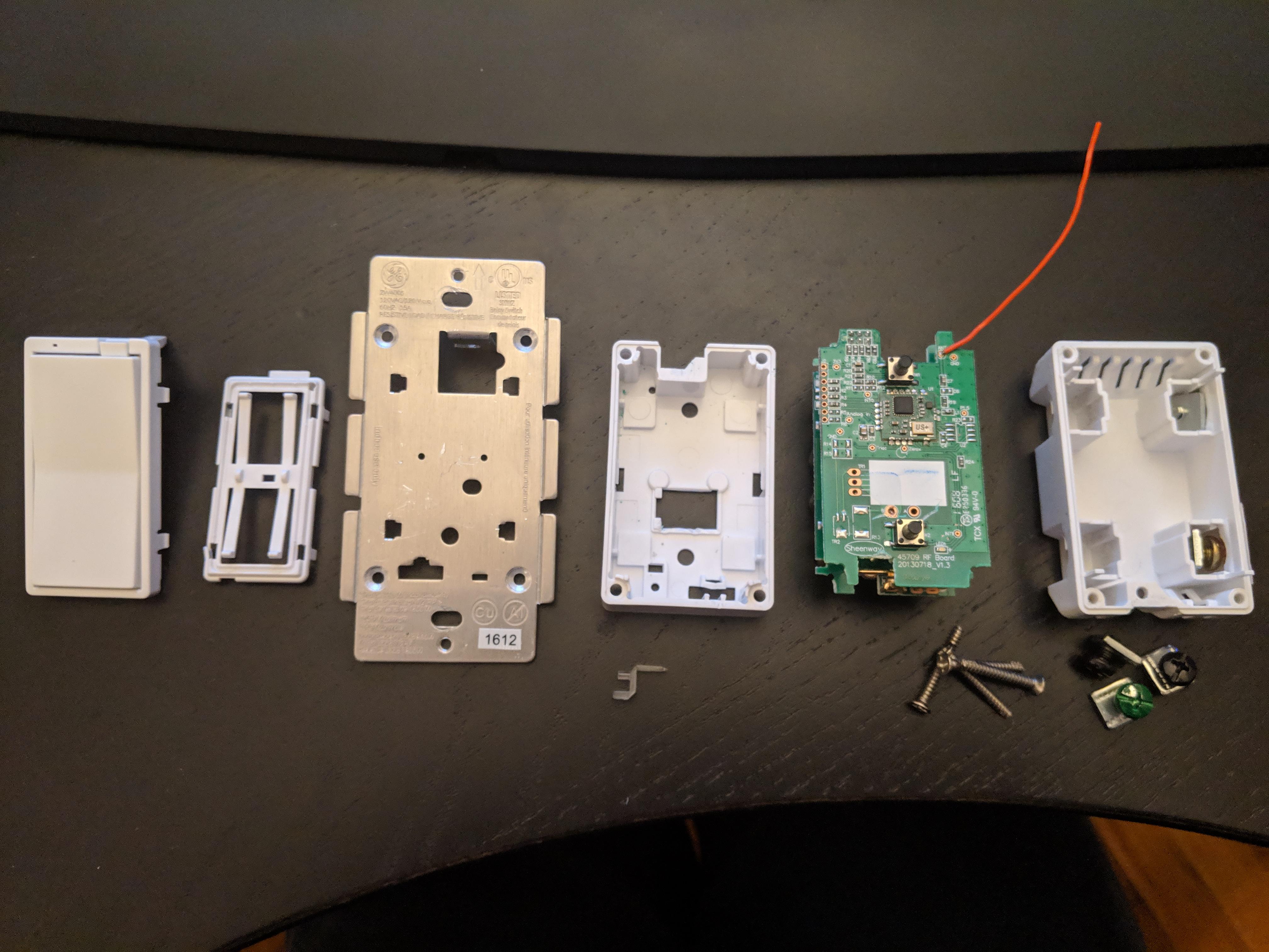
I had two die when the power was turned off (the latter when I turned off and on the common breaker when trying to reset the first). Though, they were turning on and off about one or two cycles a second, rather than just staying off as you noted in the first message. I also opened mine up (Sheenway 45709 RF Board 20130718_V1.3), the main chip is ZW0301 G1648HS, which has a datasheet at https://media.digikey.com/pdf/data%20sheets/zensys%20pdfs/zm3102n.pdf
The unsoldered header on the left (J2) connects to Notch numbers 11, 1, 2, 8, 9, 7, (not populated R5 to 10, and not populated R6 to 15). That is: VCC, GND, RESET_N, SCK, MOSI, MISO (& RXD, TXD). These correspond to ICSP/SPI. https://airbus-cyber-security.com/dumping-firmware-z-wave-asic/ details some ICSP usage on a different board (but the same chip). In my case I think the chip has gotten into a bad state and needs to be reset, so I might try tying RESET_N to ground.
(2 URL limit)
For the relay, https://www.mouser.com/ProductDetail/Song-Chuan/507HN-1AH-F-S-24VDC?qs=gTYE2QTfZfTnYx9H%2B6B77A%3D%3D has the datasheet, looks like 507HN-1AH-F-S on my board. You could check the voltage across the coil pins to see if it’s being energized, if it is then the relay is bad, but if not then something upstream (might be the main chip again).
I have two switched that went bad after a power outage.
I checked the wires using a multimeter and the switch is getting power but fails to turn on even manually.
I’m going to order some of these relays and see if I can get them going again. I’ll post back and let you all know how it goes.
Any luck with replacing the relays? Curious if that worked.
I’ve ran into this issue a few times after years of using a switch. I’ve lost 2 out 15 in four years. The first one I lost, I didn’t do much troubleshooting - just replaced. On the second, I pulled it completely apart and used 3.3V and GND off a RPi to power the RF card while disassembled. The switch registered and functioned, I could control it using the physical buttons or remotely via ST. To me, this seems to be a systemic issue with the rectifier circuitry - causing under-voltage issues converting AC to DC for the electronics. I’ll tinker with non-functional switch a bit more to see if this can be reasonably replaced but not likely.
1 Like
One of my switches died this morning. The switch kept making a clicking noise while the blue light was flashing. I took it apart and searched for the relay and found this discussion. Has anyone successfully fixed the switch by replacing the relay?
i got the four screws out of my device and removed the back cover, along with the white plastic parts on the the front, but can’t figure out how to further disassemble. there is what appears to be a rivet on the metal side. did you have to drill this out?
I didn’t have to drill anything out. I believe all that was holding it together was the screws and some plastic clips.
1 Like
It looks like The Signal Path on YouTube has finally diagnosed the issue with our ZW4005’s. It looks like a bad capacitor on the high voltage board is the culprit causing the low voltage board to not receive proper power.
I have 4 symptomatic switches myself I want to repair. I have yet to source the correct capacitor or attempt this repair but this looks very promising.
1 Like
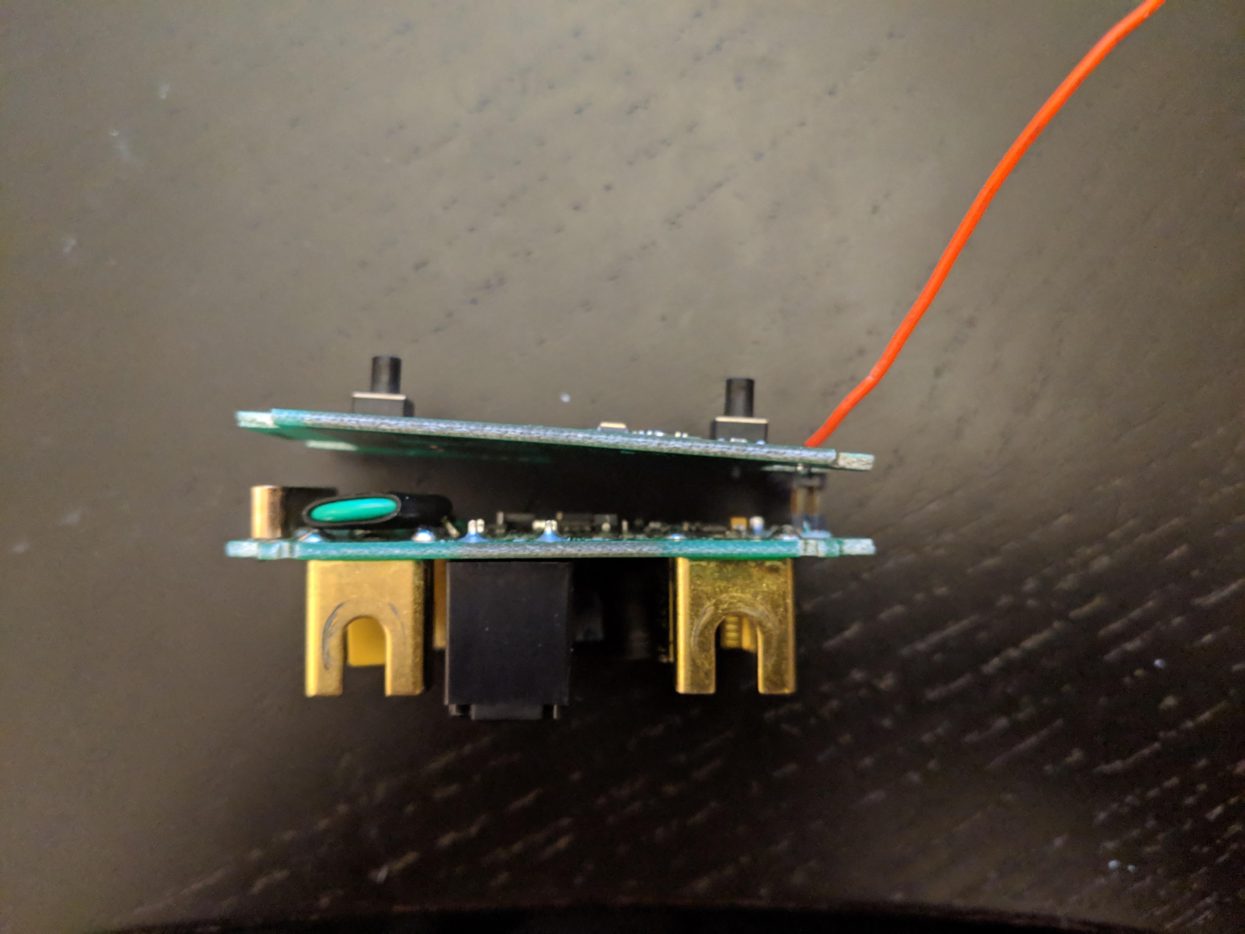
I also had a failed ZW4005 switch. After Jasco replaced it under warranty and did not want the original back I did the repair as described by The Signal Path. Measured the capacitor and it was 20 nF instead of 10 uF. Replaced with a 10 uF, 35 volt unit and the switch is working again.The hard part is separating the boards. Thanks Shahriar.
2 Likes
The other capacitors, for what it’s worth, are one 220uF 16v and two2.2uF 50v. Note that higher voltage rating is fine.
Tempted to instead disconnect the RF card, put a battery on it, and just use it as a ZWave remote. Especially since it has all the multi-click support.
1 Like
BTW, since this failure seemed to coincide with a power surge, I’ve added a whole-house surge suppressor to my breaker box. If you have a recent Siemens box they offer a unit that just needs to be snapped in and have its ground wire attached to the bus. Siemens will only warrant it to protect the household wiring, which may or may not include smart switches permanently wired in, but at least it puts a set of MOV’s onto the line where they have as chance of providing protection; I considered it $100+installation well spent when I had the box open anyway.
Hm. The relay in the switch says it’s 12v control. Is it being driven with 3V, or is there another voltage output from the power supply?
I damaged the header pins on the first switch I disassembled to repair (fixed 3 others). The relay is on the high voltage board and is triggered from a 12 volt signal, the zwave chip part of the board works from the 3.3volt. I’m tempted to do the same as you, turn it into a z-wave controller only for something else! Love the idea!
1 Like
Related to that: does anyone know how the test (?) vias at the edge of the circuit board, or other connection points on the carrier pcb, map to pins on the ZW module? Presumably the one marked analog in connects to the ADC, or would if the resistor was present…
Just wondering. It’s a cute little module, designed for a lot more flexibility than these switches need but presumably cheap enough in bulk that stocking/design/manufacturing simplicity of using a single component throughout the product line offsets the tiny amount a more tightly optimized part might save.
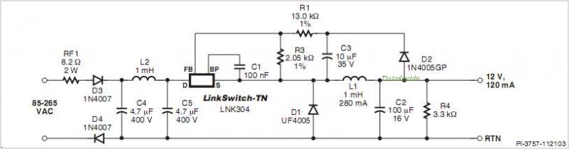
Thanks for the correction. I was trying to read them off without unsoldering them, and apparently couldn’t get a good angle. Though I’m confused since the schematic you’ve shown doesn’t seem to have 2.2uF caps. Admittedly for this sort of filtering the exact value often isn’t critical, but…