I don’t know this stuff well enough to give advice but some things that will be important to getting an answer:
What make and model smart switches are you installing. Different brands are wired differently.
In your diagram, identify the “common” terminal on your dumb 3-way switches. It’s usually black but will for sure be a different color than the other two, non-ground, terminals
I’m not sure there is only one “state” each for light on vs light off but I’m still learning about 3-ways. Showing how the individual wires are part of cables will help identify where your line and load are.
The first thing you are going to have to figure out regardless of what switch you are using is where is your power coming from i.e. the “line”. Many times it’s power > switch > light(s) > switch OR power > switch > switch> light. If that is the case, you are looking for the switch that first gets the power. Typically, that switch will be connected to two romex, one two-wire and one three-wire.
The three-way switch will have a black screw on it. The line romex’s (power in) black will be constantly hot and will be connected to the black screw. The three-wire romex’s red and black (although colors may vary) will be connected to the other two (traveler) terminals on the switch. The whites (neutrals) will most likely be nutted together.
If you find this switch, this is where your master will go.
It’s also possible that power goes to the light first, so if you can’t find the switch described above, you’ll have to look further.
Is there another switch involved (4 way). In a normal 3 way(2 switches) their will be 2 travelers between these switches, each end of a traveler would always be at the same(=) voltage. That is not what is shown in your diagram.
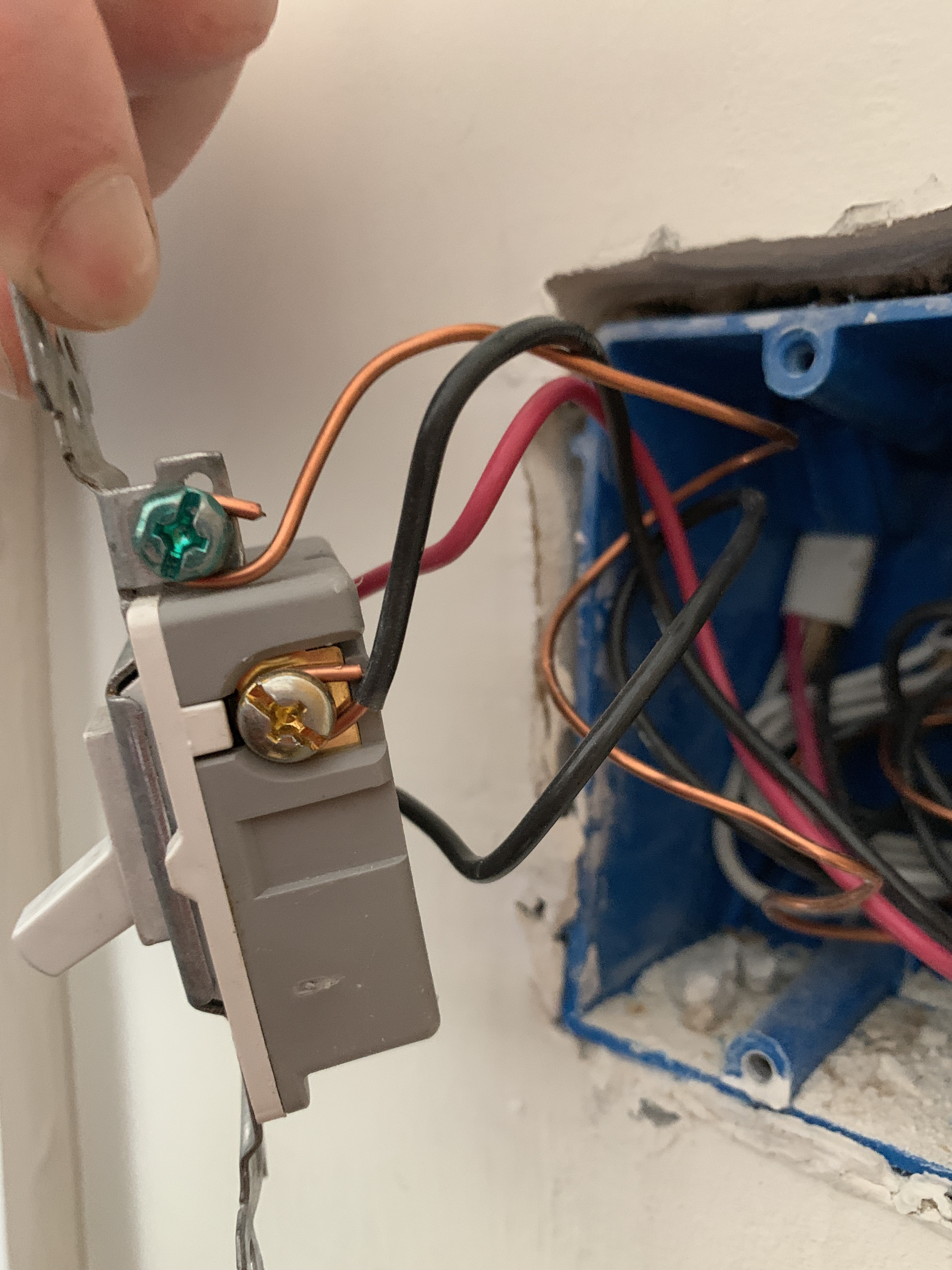
Agree with Bry the three way switches have a common screw that is a different color. With light off one of them will be hot. Based on your drawing it looks like that’s the garage switch. Please pull the switches out of the box and post clear pictures so we can see wiring inside the box.
Romex 1 is black, white, red, ground.
Whites are bound together.
Red to top left copper, black to copper top left.
The wire from the black screw goes into a different romex.
Red, black and white, with the whites bound.
Red goes to the right side copper terminal
black goes to the top left copper terminal
Black stud black wire goes to a different romex.
I attempted this setup yesterday afternoon and it did not work.
Perhaps because I’ve smoked the switch when I installed it incorrectly one of the few times I did it wrong.
OR the setup is not logical and I just can’t figure it out.
I’ll buy a new switch, and leave it to a professional.