For example, a GE 12721 has one Z-wave switched outlet. Is there a similar type outlet that has the added wires on the back of it (or load screws) to chain a regular outlet to the Z-wave enabled side such that one GE 12721 can control two outlets (the one built in and one you chain to the GE 12721)?
Use one of the z-wave micro relays inside the box and connect regular outlets to them? You won’t have a button on the outlet to manually change it (or the blue light that you can’t control for mine) but otherwise does that cover it?
Yup, that’s one way to do it but it would be nice to have the manual button. Here’s what I’m trying to do. I have an outlet next to an outside wall that I have not used in 23 years living in this house. I want to run Romex 120v wire from that outlet (replaced by the GE Z-wave outlet) up to the outside soffit (roof overhang) and install a 120 outlet. I will plug a low voltage transformer for outside garden lights into the new outside outlet. I will turn on the garden lights via ST hub but I wanted the option to let my guests turn the lights on/off without giving them access to Z-wave.
Don’t try this at home kids…but has anyone taken one of the GE Z-wave outlets and run wires out the back of it so you can chain another outlet to it? Mind you, I don’t plan on using the Z-wave controlled outlet inside the house but wanted the other receptacle available just in case someone wants to plug in the vacuum cleaner. This would answer the question of why I just don’t install a Z-wave light switch in its place…would be pretty funny seeing a light switch sitting 12" off the ground where an outlet should be.
Well, for twice the zwave devices you could put in a z-wave outlet and then run always on power over to the other outlet and either put in another z-wave outlet or a relay behind a regular one. Then use the button on the first outlet to control the second one, too (Big Switch is something that does this, I believe?). More expensive, but you get a button. Actually, for outside use I’d suggest the relay and a GFCI outlet - just in case.
Another random thought: If you could run romex in the wall up to normal switch level you could install a z-wave switch and run both outlets off of it - that way the button is at a more convenient level, too.
Hope one of these random thoughts sparked an idea.
The outside outlet under the soffit is going to be an “outside style” GFCI as you say “just in case”. I didn’t want to cut a new hole in the wall to install another switch. The outlet I wanted to use is below a three light switch box…making it a four light switch plate is pushing it I thought.
I’m waiting for someone to reply either “you dummy, you are going to void the warranty and burn your house down if you modify the GE Z-wave outlet” OR… “yes, I modified one, it’s easy to do and here is how you do it”.
Since I could not find a Z-wave outlet that provided for the capability of chaining another outlet to it I made my own. Here are the directions for modifying a GE12721 Z-wave outlet. The disclaimer: Modifying a device is something you do at your own risk and as such I am not responsible for damage, injury or death as a result of a modification using these directions or any similar modification. DO NOT DO THIS MODIFICATION it could be dangerous. Okay, now that I got that out of the way…
(1) 1st picture: I opened up a GE 12721 Z-wave outlet by removing the four screws which hold the device together. The top outlet is always hot. The bottom outlet is hot when the Z-wave device is switched on. In the first photo you can see the inside of this device. Note the red dotted circle is highlighting a lug terminal already available which is connected to the Z-wave switched hot output.
(2) 2nd picture: Shows a closeup of the lug terminal
(3) 3rd picture: SInce there is no easy and obvious place to drill a hole in the plastic packaging I decided to use one of the existing holes which is used to hold the device together. This means that out of the four screws I removed only three will be used when the device is put back together which is my opinion is plenty. Since AWG-14 wire will be used the hole nearest the lug terminal needs to be opened up a little bit. In addition, the plastic wall around the hole needed to be clipped out so the AWG-14 could be run down the hole and still allow the device to be screwed back together.
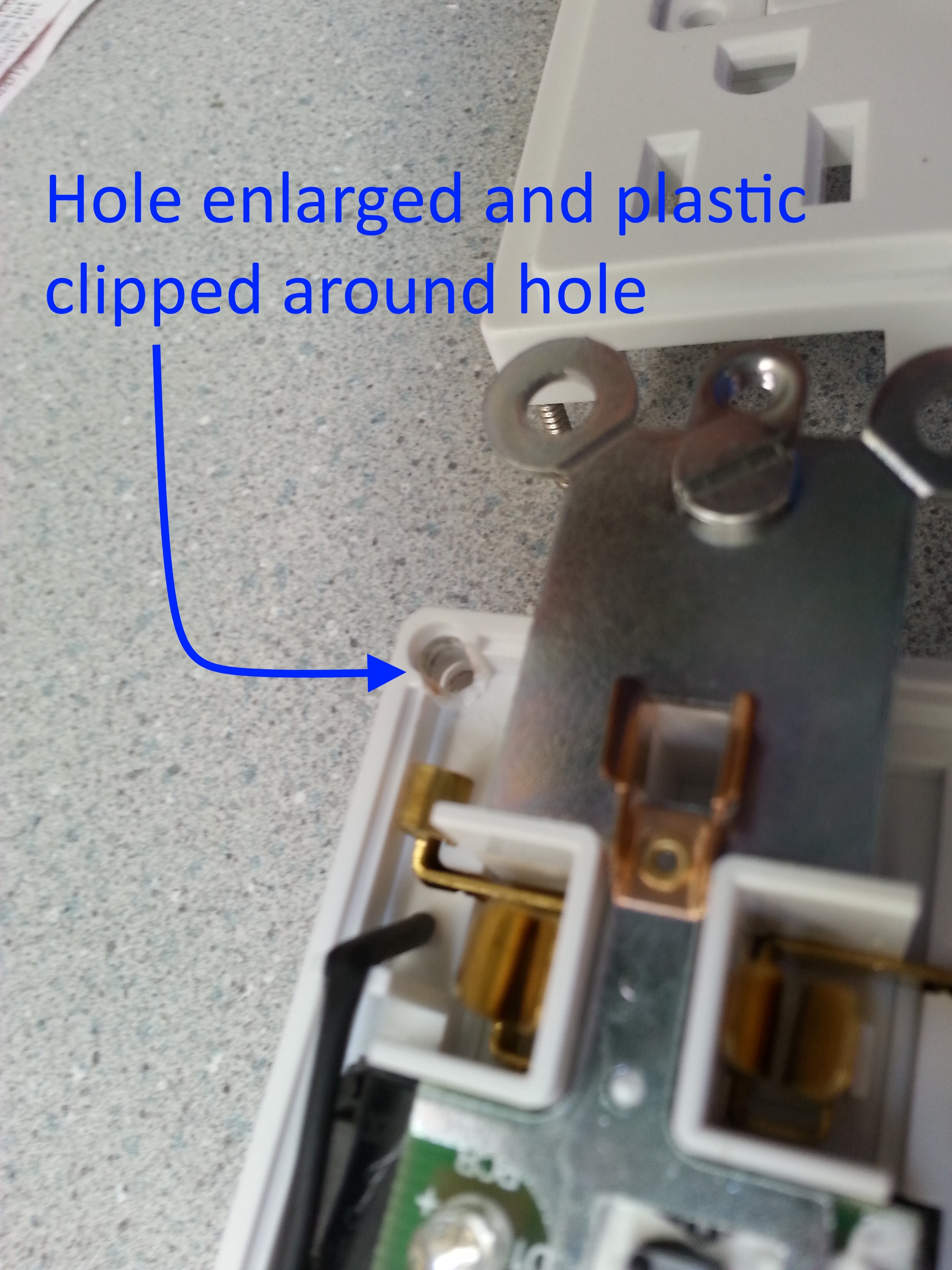
(4) 4th picture: Shows a closeup of the enlarged hole and the plastic wall around the hole clipped away.
(5) 5th picture: AWG-14 red wire is soldered to the lug terminal and fed through the enlarged hole.
(6) 6th picture: Shows the device screwed back together. The red wire is the switch Z-wave hot output. Obviously, the black wire is the hot input, the white wire the neutral input and the green wire the ground.
The way this is used is the modified device replaces a standard two load outlet which already had 14 gauge romex wire running to it. For the chained outlet standard 14 gauge romex is run from the original outlet to the new outlet which in my case is a new outlet I installed outside the house in the soffit. At the original outlet the three white neutral wires (incoming neutral, chained outlet neutral and Z-wave neutral) are all tied together. This is also the case for the three ground wires. The incoming hot black wire connects to the Z-wave hot then the newly added red wire from the Z-wave device connect to the chained outlet hot wire. When the Z-wave outlet is switched on it also activate the hot wire to the chained outlet effectively turning it on.
Recall that the total load on this particular Z-wave outlet is 1800 watts; this included both the switched and constant outputs on the outlet. With the newly chained outlet it means that the total load for all four outlets is still 1800 watts.