These two three way switches control a series of top outlets.
I connected the Zooz s2 zen 26 up as best I could figure and the lights connected to the outlets are flashing.
I connected the red (common on the dumb switch) to Line
I connected neutral to the bank of white wires in the box (maybe this isn’t neutral?)
and the remaining black and white to load and traveler (tried both combos)
I’ve worked with three way wiring a decent amount, but this seems odd.
Until @TheSmartestHouse can comment, I’d start by mapping your circuit. You need to determine where your power is coming from and the Zooz goes there. I can’t tell from your pictures which the line is coming from without the switches pulled out farther and all of the wires showing.
There technically is no required standard for wiring colors, but there are commonly accepted practices. Typically, the circuit will be powered via a black and the 3-wire’s travelers to the light/other box will be the black and the red.
I’m not saying yours is incorrect, but the wiring configuration you described isn’t correct if the commonly accepted practices were used. If you can post better pictures, the brain trust here can figure it out.
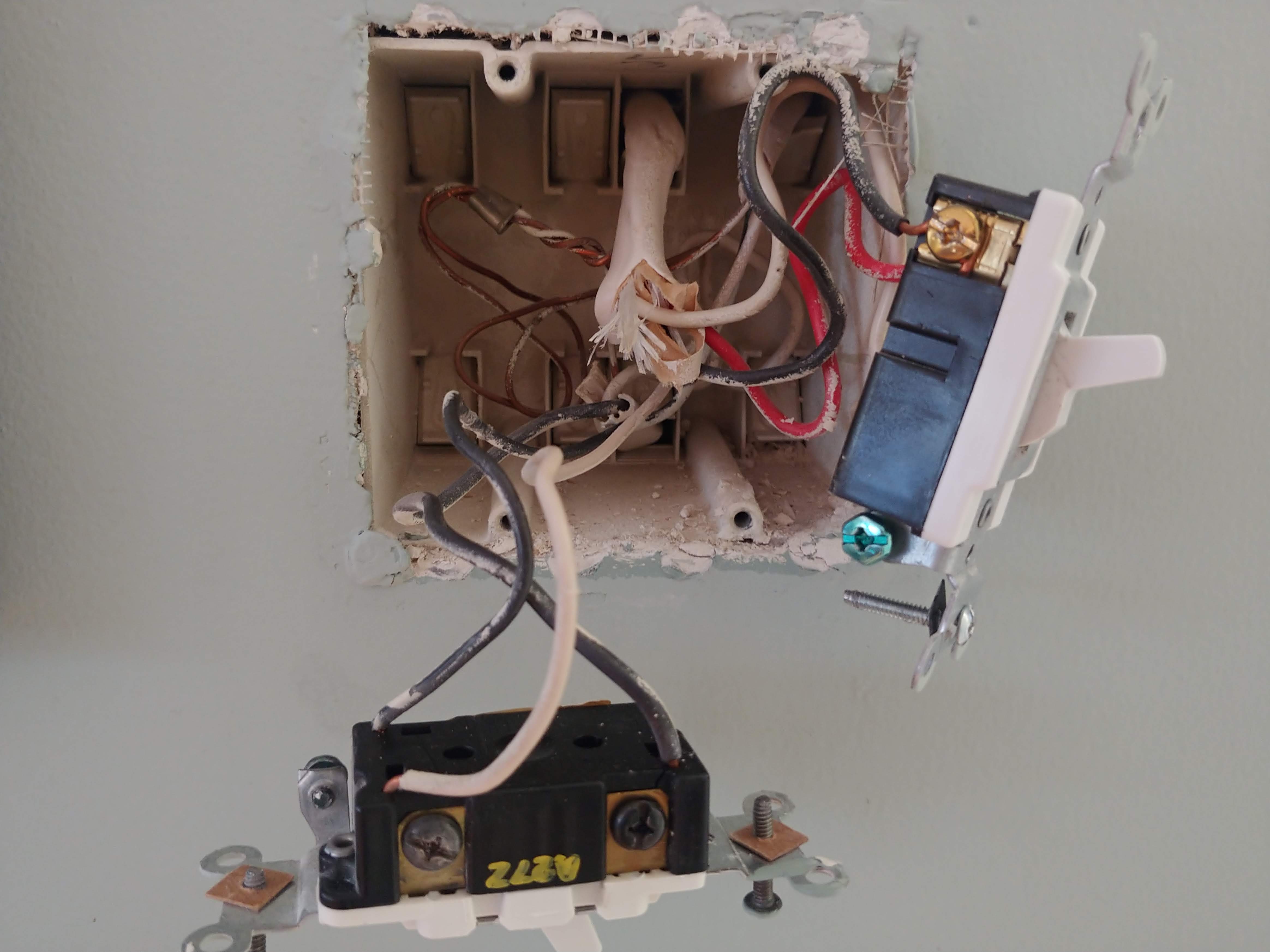
The diagram is about as clean as it’s going to get, but here are two photos showing the cluster of wiring. Note: the switches are the ones on the left.
@Jason_Day Do you know where your power (line) is coming from? I’d expect to see a 3-wire at least partially connected to each switch, but in your case the top picture shows 2 2-wires connected to it, I think.
As a side-note, you have plastic boxes, so your switches are not grounded by screwing them into the box. The NEC requires, for safety purposes, a bare copper ground should be pigtailed and connected to the green screw on each switch.
@Jason_Day this is strange looking at wires coming in from above and below on your first picture. So the key to 3 ways is one black screw is load and the other is line. Looks like line from breaker is in your first picture I believe. Follow the black wire hooked up to the black screw on the switch. What is that white wire hooked up to? It’s hard to see as if it’s just tucked into back of box. Please let me know.
Using a multimeter measure voltage of the the black and white wires of this Romex. I expect it to be 120.
@Jason_Day also I need to see the wires hooked up to that right switch in picture 2. Looks like 3 wires are hooked up to it? Thinking now you have line and load in this box and instead of using a single 14-3 wire to your other switch they ran 2 14-2 wires.
ok, so I’ve labeled the photos to match the diagram.
The second switch in box #1 is shown the in the diagram. There are four black wires into the single pole 1B switch (single switch/outdoor light). In the box there is an untethered black wire (shown in diagram).
The second switch, #2b in box #2 has a 14-3 to it. In the box there is an untethered white wire (shown in diagram).
Ok believe I understand and what’s going on now. Please use a multimeter and in box 2 place one probe on black wire hooked to the black screw and other on the white wire tucked into back of box that’s not hooked up to anything. See if you read 120.
I suspect that you have a single 14-2 going between these two switches. Then they ran another 14-2 to the closest outlet to get power to box 2. Then a 14-3 to the closest outlet to box 1. If I am right then we will need to put your Zooz switch in box 2 and hopefully that unused white wire is a neutral.
This will require option 2 for wiring since there aren’t 3 wires traveling between switches.
One thing we would add, when measuring voltage, it’s always important to have the wire disconnected from the switch (power off first). Voltage readings are not conclusive when the wire is still connected to the switch.
Agreed with @ritchierich that we’re probably dealing with a 14-2 used for travelers and the red in box 1 is most likely connecting to load.