I have a neutral bundle and a hot bundle in this switch box :-/

So you are pretty confident that you have option 9 and not 1 or 3?
Reference drawing.
Well, I was but obviously something is jacked.
One thing is for sure, I’m now confident in what each wire does.
I made a video last night detailing my tests and from what I can tell I’ve definitively pin pointed each wire run.
I’ll update with the video today.
@joshuairl here is the wiring I connected the MP single-relay to have almost 100% functionality. The only issue I have is if both physical switches are in the Up position, then the MP single-relay cannot control the lights. Otherwise, the MP single-relay works with ST and use of the physical switches also works.

Also, I found that I needed to press and hold the MP single-relay Program button for 3 seconds until the red LED blinked once prior to it working with ST.
Yeah, I definitely have that much.
Also, my relay works regardless of switch position because it’s attached to constant power via hot wires in the box.
I might have just been tired but last night had a strange phenom. that was causing one switch to not work depending on the state of the other switch.
All of my 3-ways I’ve tried are sending hot power over to the remote switch box via a white wire of the 3-wire romex with ground. It might be similar to your diagram. Except since there is constant power in the load box then it shouldn’t be flipping your relay off with the switches.
After getting the 3-way to work with a single relay, I decided to try connect my MP dual-relay to a 4-way switch (power at the switch) in the same gang box that I have the dual-relay already connected to only a 2-way switch. All I did was connect the red and yellow, and it works (again, except when 2 specific physical switches are in the On/Up position, then dual-relay does not respond).
We have a very good electrician (commercial by day, moonlights with residential) that I am going to have to go follow around some weekend on a new build so I can learn what may be causing this to not work 100%. I’m sure he’d like the free labor, lol. 
Well I can definitely tell you why yours aren’t responding when switches are in up position and that’s because your black relay wire (on the single relay and I also think it’s the same on the dual relay) MUST be on constant power at all times regardless of the switch position.
So if you have a bundle of black wires in your switch box, or get your non-contact voltage detector out and find the constant hot wire. The wire cannot ever NOT be hot for it to work. If switches turning off makes the black wire NOT HOT then you’ve got the wrong wire.
So I repeat, the black relay wire needs to be on constant power or these relays are pointless… if switch position dictates your relay device you will not ever be happy with the implementation and it kind of renders this whole thing pointless. SmartThings will always report it’s last state before those switches cut off it’s power… so you may think that the lights are on when they really aren’t… where as if you wired it to constant power you would always know the state of the lights since the load itself is only wired to the relay and not to the switches themselves.
The biggest problem I think people face with 3-way setups in regards to these relays is the fact that they traditionally do not have hot power AND the load wire in the same box.
I believe after all of this I finally fully… well 99.999998% understand wiring and how it should all work together which SHOULD be enough to make these relays work.
In my video above, I had the single relay wired into 3-way setup Option #9 as Ray keeps saying from that link he’s posting. Regardless if the switches were all up, all down, one up one down, other up other down, the relay and the light switches all worked together to toggle the light in the opposite of what it’s current state was.
This is how it SHOULD work. If it’s working in ANY OTHER WAY then it’s not wired correctly and is fairly pointless to even have it hooked up in my opinion. I see zero benefits to using these hidden relays if your switches dictate the relay’s operation…
That being said, I won’t stop until I nail this down and get definitive diagrams that show all 9 of the 3-way setups with how these single relays can be wired to be made to work. Most of the setups, however, will require extra power to be ran to one of the switch boxes or the fixture depending on the existing setup.
I believe I’ve got lucky in my house in the sense that all of my switch boxes have either constant power already in them or there is constant power close by that I can tap into and run to the box to feed the relay.
My only existing issue at this point I think is this ghost issue I’m having in my walls wiring. I’m guessing either I just flat out don’t understand circuits (which I don’t think is true) or I don’t understand all the crazy assed possibilities that could be lurking behind my walls.
All of that being said, I have a video showing my setup in my basement that I think is very valuable to painting the picture of just how my basement is wired. I’m going to upload the edited video now and post it in a separate post.
Alright team!
I made a new video for my basement wiring since this time I thoroughly tested (at least to my knowledge) all of the wires in both of the boxes I’m working in and have somewhat definitively painted a picture of my wiring setup… at least I hope that’s what I’ve done.
I added annotations and speech bubbles to show you exactly what everything is doing and what I was doing.
I also physically labeled all groups of wires at the end so I can remember what each group goes to.
Let me know your thoughts if you get time. I know I’m not the most entertaining to listen to but if you watch the full video and don’t skip ahead I think it should paint a decent picture of my wiring setup for my basement as it pertains to installing the single relay on the 3-way for the main lights in basement.
I am just guessing but sounded like that’s the case by looking at their manual for a single relay. You can look at the solder trace of that wire to the relay base if you are curious.
That’s very well explained in the video. You sure don’t have much luck but sounded like you know 3 ways really well now. Here’s something to try. How about using the 3 ways wiring as a 2 ways for testing and leave the switch at the load box out of the circuit.
Use just 2 wires at a time. Not that I don’t believe you with your finding just that I haven’t seen this before.
In case anyone was wondering what insanity looks like…
Some people say it’s when you do the same thing over and over expecting different results…
And here are those results…
The video I just posted shows the 3-way wired outside of the wall and inside the wall but second time it only uses the 3-way wire plus wall outlet plug to power it.
Can’t figure out what I’m missing…?
Alright… I’ve determined my 3-way wiring setup is NOT Option #9
There is absolutely no way it’s Option #9 or it would just work as it does outside of the wall wiring.
There must be something different about that white wire that runs over to the other switch, or the neutrals, or something. I’m guessing it’s the neutrals that is throwing it off.
I did ACCIDENTALLY get it to work though.
I had all my hot bundle + neutral bundle running off of a wall outlet AC cord for the basement.
I had one switch out of the wall hooked to the AC power cord as well.
I used the white, red, and black wires running to the other switch.
Wired it for Option #9.
It wouldn’t work.
Then I disconnected the WHITE wire from the remote switch and it started working…
I then discovered that I had the white wire on the main switch wired to the white neutral source wire coming from the breaker… or at least I think it was coming from the breaker? Once I fixed that, it stopped working again.
Maybe I’ll draw up a diagram of how I had it working. I’m guessing it was one of those situations where it was “working” but probably not a good thing and probably not up to code. And potentially could have been unsafe.
I’m most likely going to get an electrician out there to help me understand my wiring so I can make adequate decisions about how to wire these things.
But I WILL NOT give up or settle for sub-par functionality of my switches just for Z-Wave. I want my switches to work as they always have, as well as the relay to work in tandem. Anything less, is making my house dumb - not smart.
Having to control my house from some kind of z-wave only switch or an old iPod Touch duct taped (i know I’m exaggerating) to my wall is not a solution to me.
Just saying 
Hello Joshua…
Just thought i’d let you know that I was having similar issues with a Monoprice dual relay Z-wave device on a 3-way light switch that I just couldn’t figure out. I watched all your videos and followed the tips others were giving you on this forum and finally got it to work flawlessly for several hours, but then it started acting up… flickering lights, etc… REALLY FRUSTRATING! Then it would start working again for a while. Had this feeling that it may be ground or neutral related… Anyway, since the control wasn’t reliable I finally decided to bite the bullet and purchase a 3-way GE light switch set (with a master/slave 3-way set up) which worked really well and freed up my dual relay to control other things.
1 Like
Yeah, sadly, the thing about it is… it SHOULD work theoretically. And it DOES WORK when I don’t wire it with the house wiring lol. I may just need to get an electrician in there to help me figure out what the wires are doing.
Just curious, did you go with the Toggle Switches or the button version?
I don’t want to have to replace the wall plates too just to accomodate Z-Wave. All my switches are toggle switches. :-/
I know what you mean… it was driving me nuts! Wish you luck!
Purchased the toggle switch version (although it acts like a momentary press), so that it would match all my other toggle switches in the house. Can’t even tell the difference, except for the tiny blue light at the bottom (which you can control on/off). I think you can get a “set” for about $60 bucks or so. They work really well, so the WAF (wife acceptance factor) was good! 
Hey folks. I wanted to share some positive news.
Like many of you, I have been struggling to get my 3-way switch set up working with the zwave relay (Enerwave single relay). The big challenge I have is the main and the load are in different gang boxes - most of the wiring diagrams have them in the same box. I also have 14/3 romex going between the gang boxes for the travellers, but all the diagrams I have seen have need an extra traveller.
Long story short - I got it working tonight! Below is my diagram. Sorry so crude, but hopefully it helps someone . I encourage anyone to try this in their 3-way switch setups.

Let me know if it works for you.
Wes
@wesgurn -
This is exactly my configuration as well, and I have been racking my brain to think of a solution. It looks like your solution works for the Enerwave single relay, but my Monoprice single relay only has 6 connectors (1 short of the 7 in the Enerwave). Any idea if there is a way to connect the Monoprice in the same configuration?
@tallac -
I’m not sure exactly what the difference is. I haven’t tried it with the monoprice relay. Looking at the wiring diagram for the monoprice relay, it appears that it probably is still possible to set it up, I just don’t have one to test with or know what the wires map to or what the missing one is.
If you find out what it is or get it working let me know. Will be good to have it as a reference point for folks.
Wes
Not sure if this is still useful, but I have a few of the Aeon Labs micro double switches (http://www.thesmartesthouse.com/collections/aeotec-by-aeon-labs/products/2-aeotec-by-aeon-labs-z-wave-micro-double-smart-switch-dsc17103-2-pack) and have it wired into a 3-way config. I contacted them to ensure this was safe and the below is the diagram they sent back. Let me know if you have any questions and hope this helps.
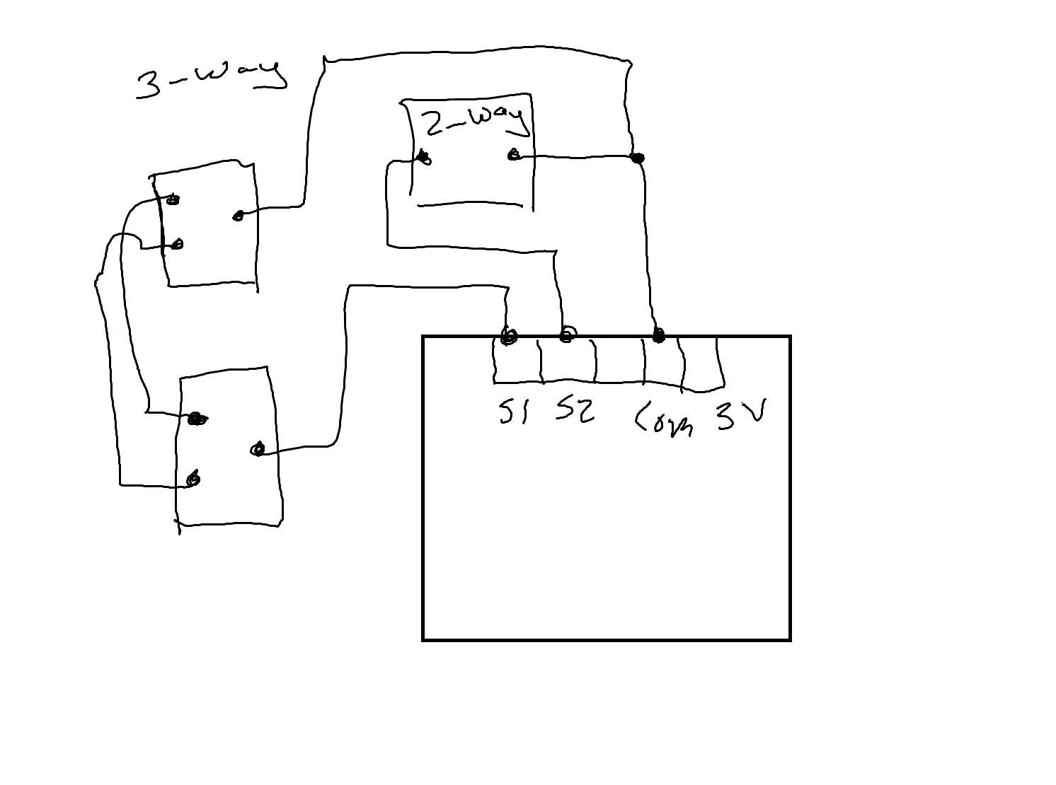
1 Like