I’m with you! I did try with blue only and black only yesterday sadly and the relay module is just MIA without both… No idea why both are required…
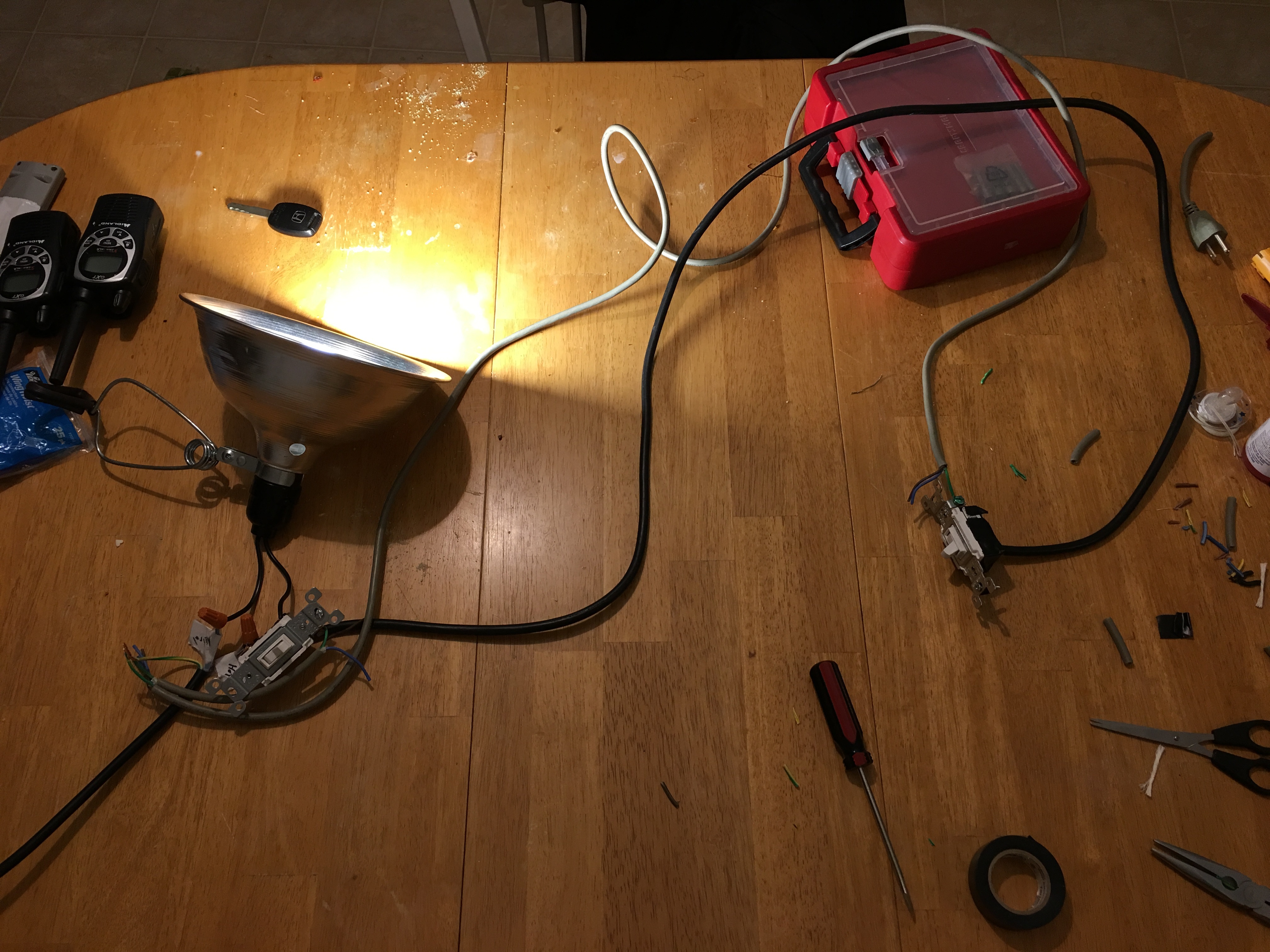
However, I’m wiring my own kit on my table right now so once I get this built I’ll test it again in the controlled setup just to be clear on what’s going on.
Alright, I’m sure there is better way to test this but I hooked 9v up to red and white of the 3-wire romex going from second switch to the first switch and tested at 9.5v so then I did white black and red and same thing. So I’m betting the 3 wire is going directly from switch to switch… I guess only thing left to check now is if the 2 wire cable going up to the fixture is good?
If so I have no idea why it’s not working in wall versus on my work table… Haha.
Guess without further ado I must hook it back up the way I think it should be in wall and try it again…
This time I’ll use the diagram “option 9” which is what I used for the work table version and see if it magically starts working. Praying it does so I can put this to bed. And myself to bed.
Something just isn’t what I think it is I guess… When I wire it up with the wall wiring how I did it with the work table it’s just doing the same thing it used to do… Guessing the only question mark is the fixture wires?
Could it be that something isn’t grounded correctly?
Why don’t you just do continuity check each wire? Easiest way is. With circuit breaker off and all wires remove from terminals of both switches. Measure resistance of each wire to ground wire. You should get Meg ohms or open circuit. If that’s the case. Now measure each wire between switches by short one wire to ground at one end and measure resistance of that wire to ground from the other end.
Side note. You tested those 3 ways switches I hope?
Yeah, the switches I used on my work table version of the setup was the same switches from the wall.
This is the video of those same switches wired into an outlet plug with the relay and it works perfectly as it should with 3-way wired like “Option #9” which is what I THOUGHT was how my wall was wired… but something just isn’t jiving.
I did that test I mentioned earlier to see if all 3 of the wires from the 3-wire cable going from switch to switch was actually going all the way there… and it seems to be. With the power off, I used a 9V battery to run the voltage through the wires to use my voltage meter on the other side to see if it read the voltage and it does with all 3 wires. I’m guessing that means they go straight from box to box… but I guess it could be going somewhere else and getting screwed up some how?
Any way… I think at this point unless you guys have anything else I can try to figure out how these wires are ran I guess it’s time to close down this topic since the relay technically does work as it should and my switches work as they should when wired correctly…
I really am so sorry you guys have devoted so much time to this with very little payoff.
I really really sincerely appreciate your time and your efforts to help me diagnose this. It’s been a fun ride.
I may try a different 3-way switch setup in my house and see if it works in that one.
In the end, given the right wiring setup, it does work and can be made to work in a lot of different setups as long as it can get constant power. Results may vary!
Again, thank you all and especially @Snakedog116 and @Navat604 for your persistence and checking in on me.
You guys are great!
I’m glad to hear that it works right on your test system.
Best of luck finding the issues in your home wiring. I would suggest you go to each wire and use your multimeter to confirm that everything that is supposed to be hot is hot, and everything that’s supposed to be neutral is neutral. You sound like someone who won’t give up. I’m curious to hear when you’ve found the issue what it was.
Let us know if you find anything that’s not as per the diagram and if you need help redoing the diagram.
You are welcome for trying to help. The nice thing about ST is the community that exists to help eachother… I suggest that you see if you can’t find somewhere to give back. (I know that the Ecobee community would love a smartapp that syncs up the thermostat’s climate settings (Home, away, sleep) with the ST states (Home, away, night) etc.) (See @StrykerSKS’s code)
You said you are a programmer, I’m sure you can find a place to help out!
I’ll leave this open until you post what the solution was
This question is a little silly to ask now but you are using the line hot and neutral of the same bundle right?
How about using another line hot and neutral for this test? You are the one doing all the hard work. We are just typing on our smartphone so it’s much easier.
Thank you thank you. Yep, I have much plans to contribute code as soon as I can find a good thing that is missing to jump in. That’s a cool idea, I currently have a Nest Thermostat but would love to help the Ecobee people somehow too. I’d guess I’d need to get me an Ecobee first haha.
Well, the work table testing was done with an AC power cable plugged into a wall outlet. This was a very stable and predictable way to test it. However, I guess I could provide power to the light in the ceiling with the wall outlet setup but just using the load wires of the fixture instead of running them to the hot / neutral bundles in the wall. Is this what you are suggesting basically?
You cannot use two different line hot or neutral on one lighting system. I am saying you should remove your line hot and neutral of the switches and light and test it with your wall outlet power cable.
Yes, I think we are on the same page. I may not have worded it as such but I do understand what you’re getting at.
Thanks Ray! I’ll give it a shot sometime soon.
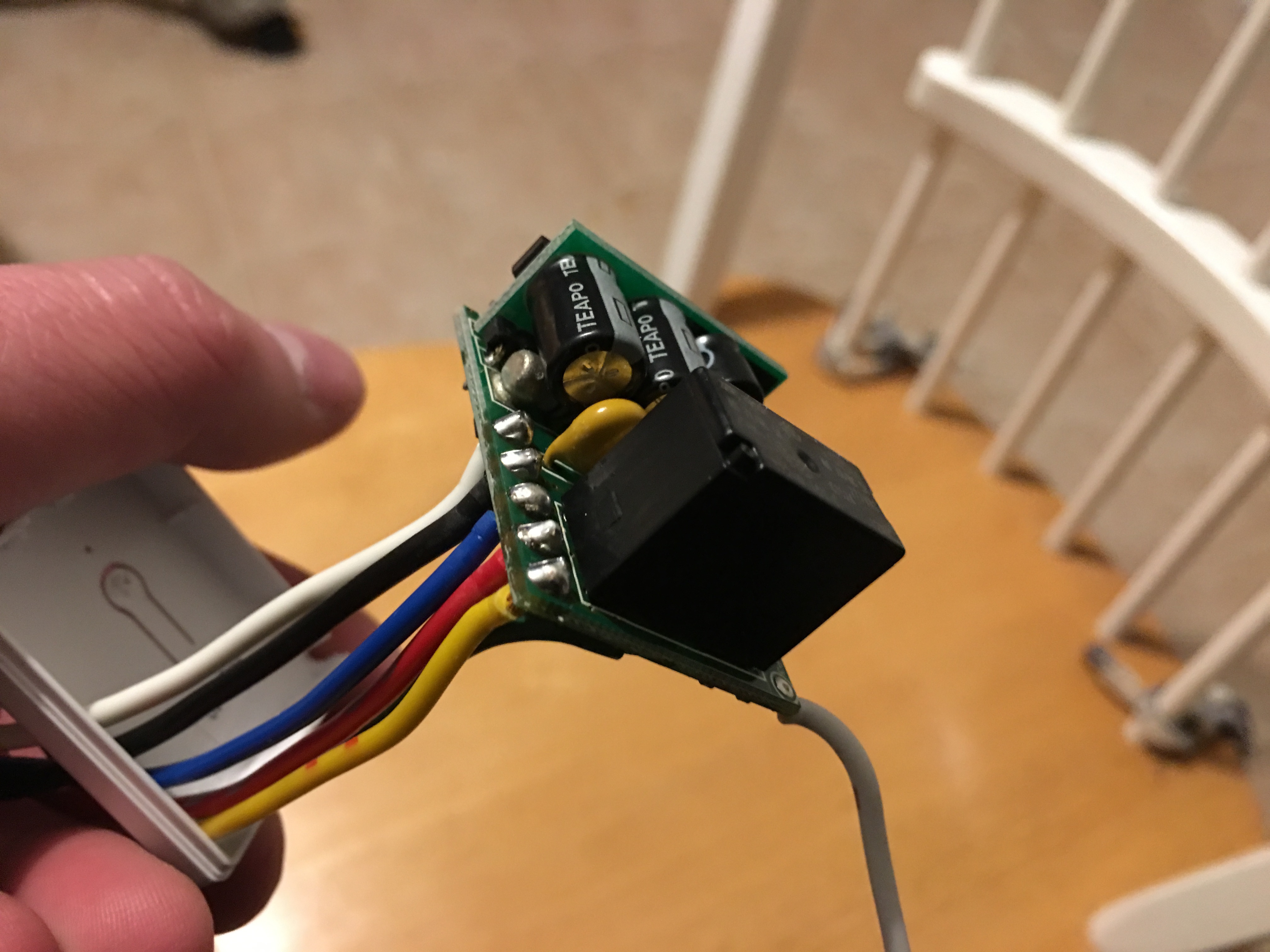
Sounds like Monoprice design choice going with the bulkier chip configuration was kind of dumb.
I prefer the skinnier Enerwave devices because they slide between two switches better. That’s my take on it at least.
This time I’m looking into my basement area.
I have loads of opportunities to add wiring in these areas.
I have a finished side of my basement and an unfinished side. All switches have exposed walls behind them so I should be able to take plenty of time and figure out the wiring in these areas.
I may also be able to feed up more power wiring from the unfinished areas of my basement to the 3-way’s on the first floor so I’m guessing I should have a lot better luck now.
But have yet to figure out that ONE specific wiring setup that was screwing me up the other day.
Alright!
I’ve wired one in the basement how I think it should be working.
I thought I had it but something is definitely off.
If the non-load switch is in the down position then the load switch works fine. But if the load switch is in the down position then the non-load switch doesn’t work.
Obviously I’m missing something AGAIN.
The relay works fine regardless so obviously it has continuous power and it’s wired to the load wire.
The green wire is on the black common screw which I thought was going to give me the on / off state to the load since the load wire was connected to that originally.
Actually, it’s basically doing the exact same thing it was doing in the kitchen 3-way situation.
I’m seriously now wondering what to do next hahaha…
UPDATE #1
Oh and also, it does the thing too where when I flip the load switch down and have my black multimeter contact touching ground wire and the red contact touching the black common screw it goes from 120 to 45 and makes the relay toggle.
UPDATE #2
Removed blue wire of relay from hot and the relay has power and clicks but light doesn’t come on. That tells me the blue wire is the input for the hot and is switched on to the red when the relay toggles on?
Same behavior as before. Switch half way in middle and it clicks on and then back off when it gets to the other position…
Just curious. How do you know which 3 ways wiring configuration you have? Sounded to me like you are missing a neutral. Possible your neutral is at the light fixture.
As for the 120 to 45 vac. What kind of meter are you using and are the probes in the right slots for measuring AC voltage?