@ritchierich Woohooo!!! that worked. You’re a genius. I seriously and truly appreciate your guidance. Can’t thank you enough.
For the record that little white pigtail hanging off of the red bundle was there because I tried jumping the red to traveler during one of my renditions of this.
I think I will make my switch fan smarter very soon so I will definitely remember that the black in Romex 1 is load.
Ok, I have another one that I want to get some guidance on. I haven’t disconnected anything yet as I wanted guidance. I suspect I need to rewire this to get it to work with the GE in wall smart switches and the add-on switch.
I have a switch at the front door and another in the garage that controls 3 lights at the front on my house (1 on the porch and the 2 outside of the garage).
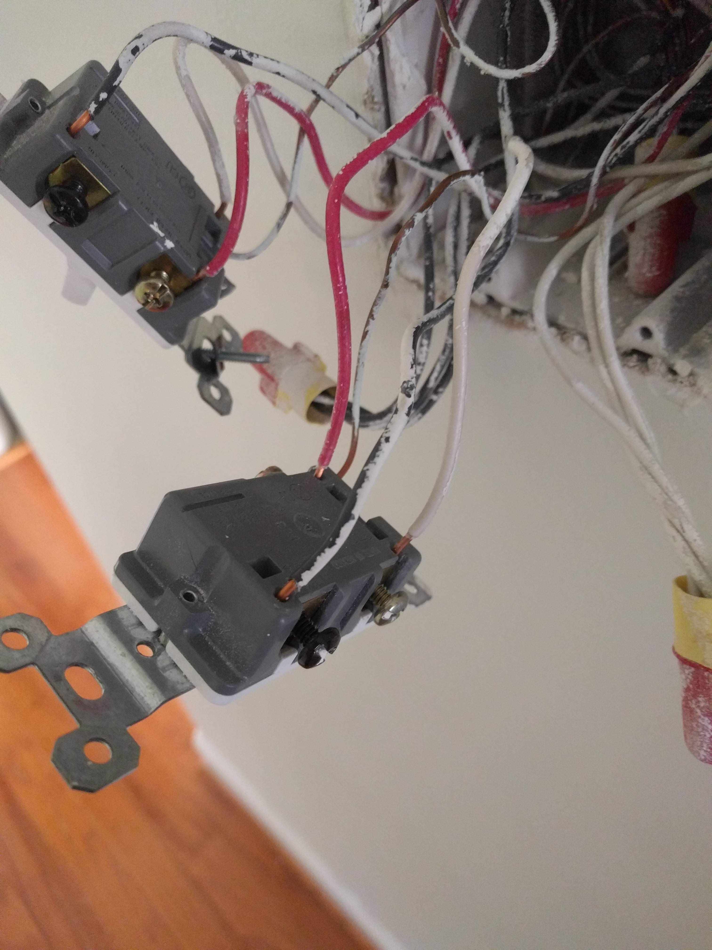
The first pic is a gang box that has 2 switches and a total of 5 Romexes. The second pic is that of switch in the garage that also controls the front lights on my porch and garage.
#1 is a 3 wire with RBW wires - red is in a wire nut with a black wire from Romex#2 (hard to see in the pic). The black and white wire from #1 connect to switch on the left
#2 is a 2 wire - black connects to the red from #1 in wire nut. White connects to a bundle of 4 whites in a wire nut.
#3 is a 2 wire - black connects to the switch on the left and white connects to the bundle of 4 whites in a wire nut
#4 is a 2 wire - this is line and neutral - black connects to the switch on the right and notice that there is a jumper from that one to the switch on the left. White connects to the bundle of 4 whites in a wire nut
#5 is a 2 wire - I believe this connects to the light in my foyer. Black connects to the switch on the right and white connects to the bundle of 4 whites
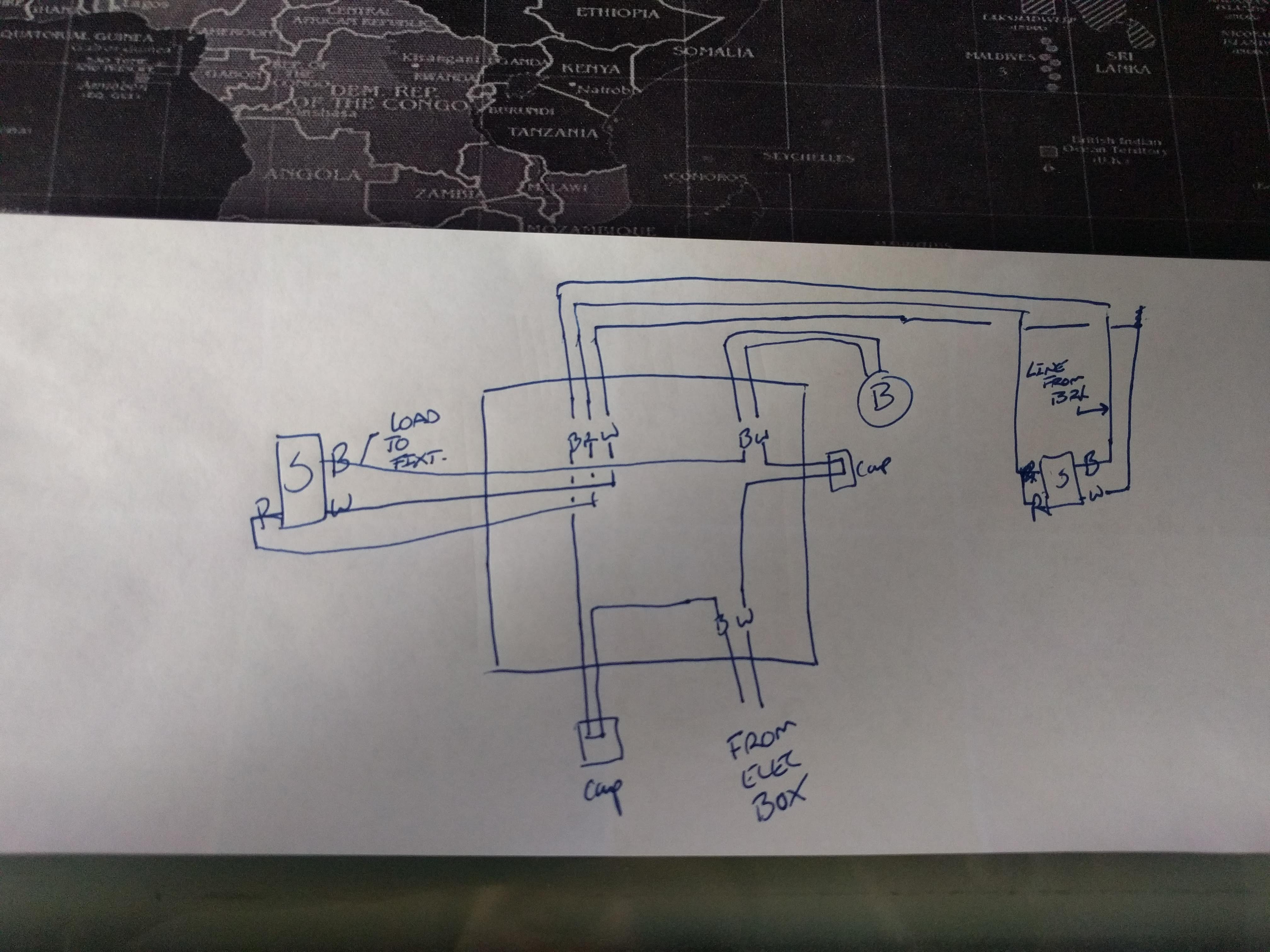
I’ve determined that capped Neutral is in fact hot…the image attached is my current wiring with the panel going to the fixture first. Am I able to rewire the light and switches to have the neutral in both light switches?
Sorry for delay, traveling internationally at the moment. So looking at Picture 2 you will see there is a red wire hooked up to the common screw (black color). Again 3ways have load to fixture on one 3way common screw and line from breaker on the other 3way switch. I believe Romex 1 is going from Switch 1 to Switch 2 because black and white are both hooked up to this other switch and the red wire is hooked up to another wire within the switch 1 gang box.
I believe Romex 2 is your line from breaker, please verify this by using a multimeter where you remove the wire nut and put one probe on this bundle of wires and the other on the ground wires or the white wire bundle. If this indeed has 120v proceed…
Look at Switch 1 and find the black screw, that wire is your load to your fixtures - black wire from Romex 3.
So hook up the following
Switch 1 needs the master switch:
Romex 3 black wire is your load on master switch
Put a white pigtail wire into the neutral bundle of wires and hook up it up to the neutral terminal on the master. Also get the white wire from Romex 1 and put it into the second hole on the neutral terminal
Disconnect the wire nut that has the red wire from Romex 1 and black wire from Romex 2
Black wire from Romex 2 is your line
Red wire from Romex 1 is your traveler
put a wire nut on the black wire of Romex 1 as its no longer needed
you can optionally turn on the breaker to verify the switch works.
Switch 2 is your aux:
put a wire nut on the black wire as its no longer needed
red to traveler terminal on aux switch
white wire to neutral on the aux switch
Thats it, just like the other switch. Again just to teach you how to fish
pay attention to the black/bronze/different color screws on the 3ways, one will have line and the other will have load
line and load are usually 14-2 wires with just black and white, exception is fans where a 14-3 wire is often used so you can have separate switches for the light and fan.
just because one of your 3way’s common screw is “hot” with 120v doesn’t mean the line is in that box. It is often “sent” to that switch from the other gang box just like with this situation of the Romex 1 red wire being connected to the black wire of Romex 2
Unfortunately you have power going to the fixture first and this limits your ability to “smarten” your switches. Most smart switches require line, load, and neutral (3 wires) and in your situation you don’t have enough wires to make this work - there is no neutral going from the fixture to your switches. If you can fish a new Romex wire to your switch that could solve it. Or read the top post of this thread for other options like micro relays that you install in the fixture box. Lutron Caseta has dimmers that don’t require a neutral but that also requires a Lutron hub.
Thanks Michael. Frustrating, but will return these. I have ordered QTY 1 of these, Lutron Switch - No Neutral I would replace QTY 1 of the switches, per Page 5 3-way install. It seems like I MUST install that with the Neutral (hot) switch wired to the load side since it’s the constant-hot load side from the fixture?
@ritchierich, So I tested Romex 2 and I don’t get 120. I think that’s because I actually get 120 from Romex 4. If you notice the black from Romex 4 connects to the switch on the right (pic 1) and there is a jumper from that switch over to the black screw on the switch on the left. This is kind of tough to see in the pic but there are two wire connected to the black screw on the switch on the left.
Correct me if I’m wrong but I don’t think this changes anything, I just will have 2 wires plugged into line on my master. Right? Meaning the black from Romex 2 is still my line, but it get’s it’s power from the jumper wire that will plug into the second hole?
Hello, I have been reading through this thread, but cannot locate my situation. I have installed a few stand alone GE Jasco Zwave switches with a black line in and a black line out. I used the white cable that came in the switch box to tie into the bundle of neutral lines.
I am trying to install my first three way switch, but cannot locate this situation. Both switches have a black line in and a white line out. Is this a typical wiring scenario? Is there a diagram available for how to install the switches?
Actually look at picture again and specifically at the black “common” screw on the switches. On both of these switches there is a black wire (color doesn’t really matter), the other two wires are “travelers” to the other 3 way switch. On the other switch you will also find a black common terminal too. It’s important to know which Romex wire that is hooked up to the common terminal. Does it go up and out of box or is it going to a bundle of wires within the box. As I have mentioned in many posts within this FAQ, One switch will have line from breaker and the other will have load to fixture. But often line and load are in the same box and one is “sent” to the other switch.
Is that just a 14-2 Romex with black and white? Does the white wire of this Romex go to a bundle of other white wires? If so this is likely load to your fixture.
Where does the black wire of this Romex go? To a bundle of black wires? If so that is “sending” line power to your other 3 way switch. Again line on one switch and load on the other.
If my assumptions are correct you have line and load in this box, please follow instructions in my posts above on hooking this up.
Here is a crude drawing of the box and switch in the photo above. The switch with X NA next to it is for another light. The add on switch (I think its the add on side) has a black red and white wire in it only. I am assuming, based on the diagram that the add on switch bundle of wires is coming from the top left of the box.
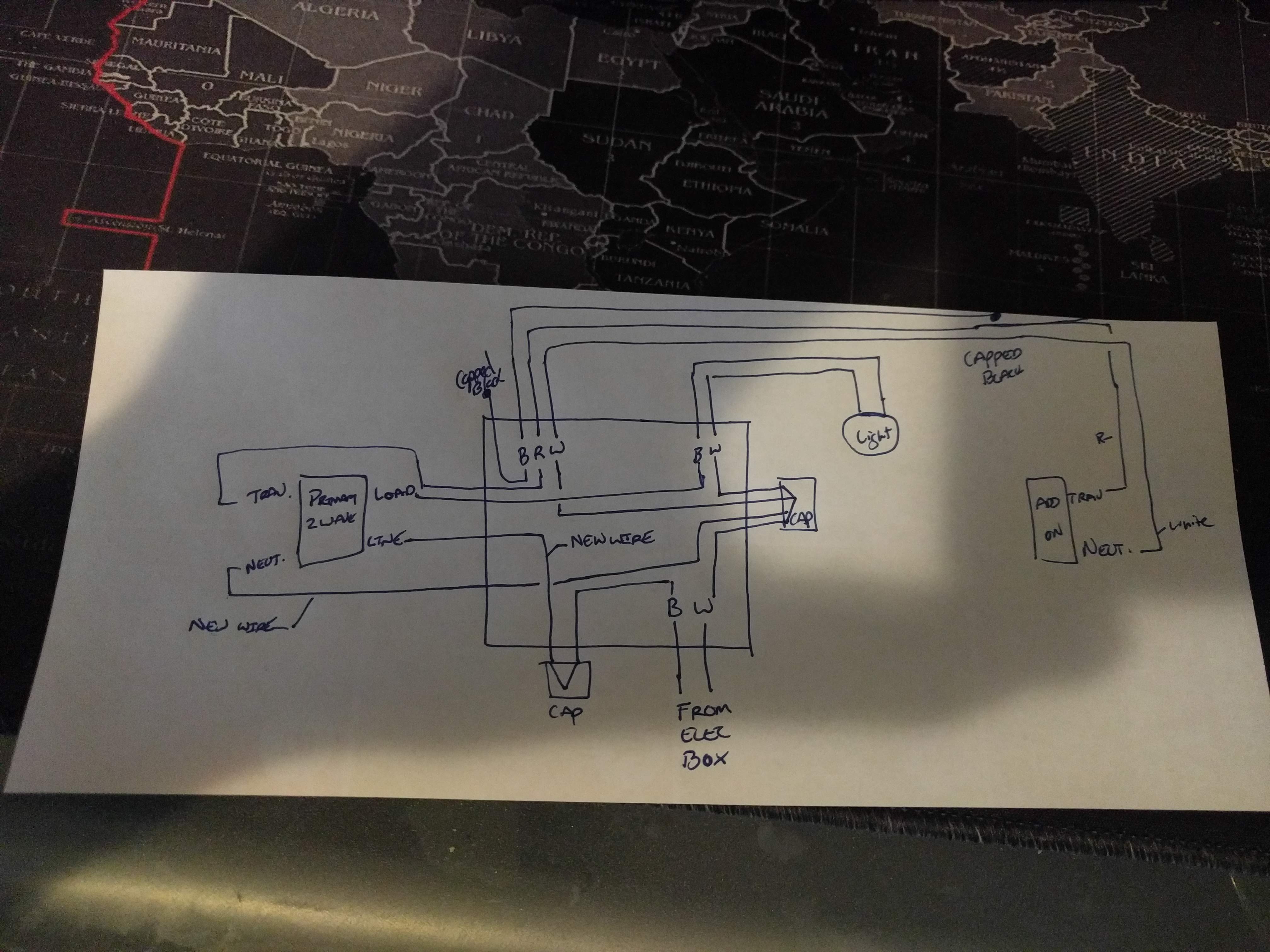
I’ve removed the switch that isn’t involved and added the add on switch and light fixture based on what you said before. I believe this is how everything is wired. I am now looking for you post about how to tie in the zwave switches.
I appreciate the work that has gone into this thread. Replacing my existing 3 way lighting switches with GE devices is really making me feel stupid though.
Both of my switches look like the attached picture.
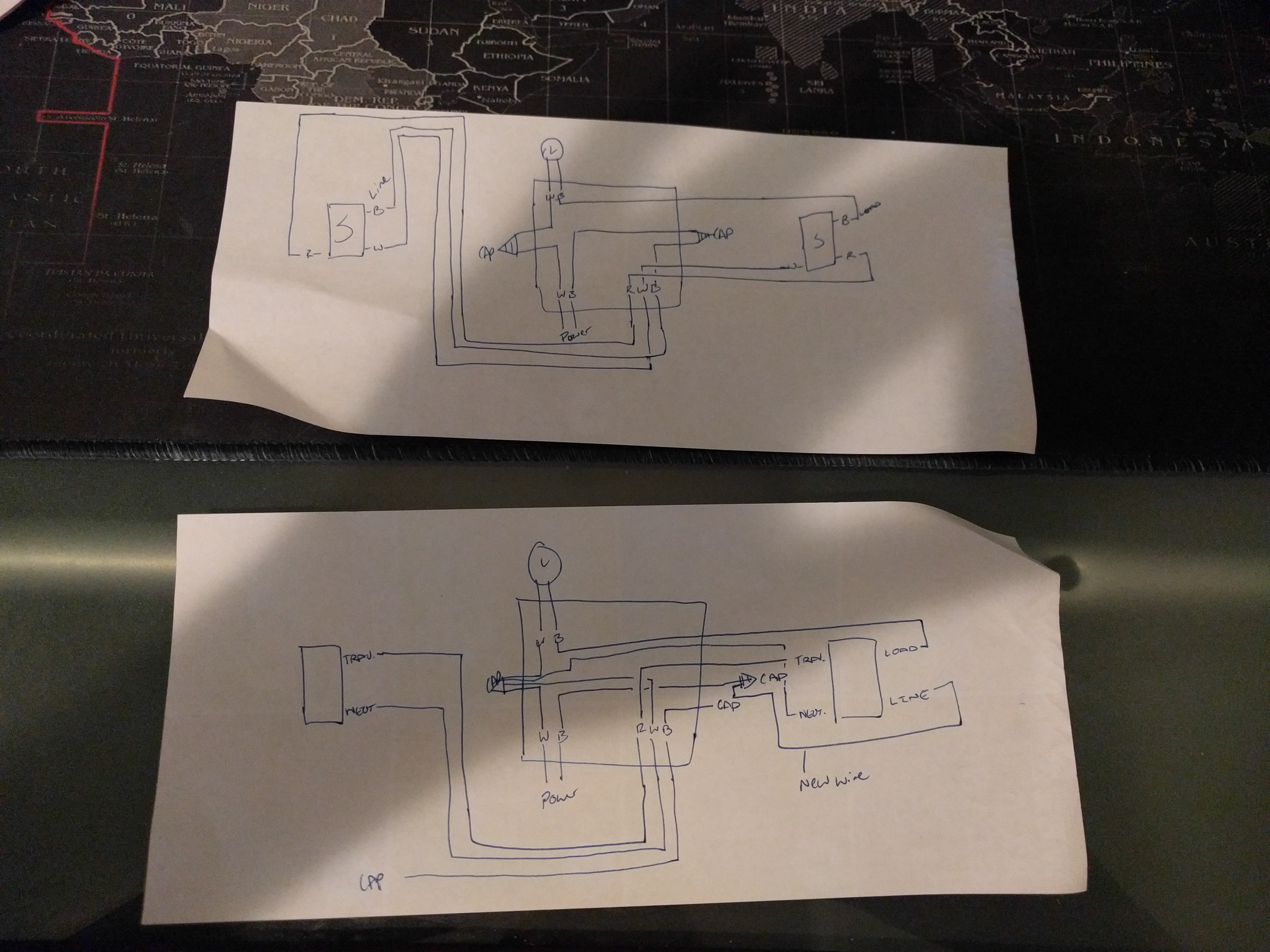
I have a sinking feeling my 3 way is wired as follows:
How can I check with a multimeter?
I have neutrals and grounding is to the box so no issue there. I have installed other smart switches without a problem, but this is throwing me for a loop.
For one switch, all 3 wires go into the same conduit, on the other switch, red and white go into one conduit (to the 2nd switch I’m guessing), and black goes into another conduit (to the fuse box?)
Thanks in advance, apologies for my ignorance. I’d really rather figure this out than pay somebody to come out and do it.