Anything basic will do.
You’ll be using it to test for 1) 120 VAC and 2) Continuity.
Anything basic will do.
You’ll be using it to test for 1) 120 VAC and 2) Continuity.
Simple/basic is fine for home wiring work. I got this one.- currently $16 bucks
Just wanted to say thank you for taking the time to provide such a detailed explanation. I was ready to pull my hair out before I found your post. Thanks.
hi guys. I am not handy and have never replaced a light fixture but i have been reading this and am thinking of trying it. I am looking to replace my dinning room switch which is a dimmer know & the other switch is an on/off. I gave a ge zwave plus dimmer & add on switch. As I understand it, adding a smart switch is different then just replacing the 2 switches with new ones. What I would look to do is use the dimmer to replace the knob and the add on where the on/off switch is. If i am reading this correctly the add on is not to be powered & just hook up the other 3 wires. I am also going to stop at lowes & buy those caps for the wires in case i need them. What I will ask is when I get home tonight i was going to screw off the cover & take a picture & post it here just in case I have wiring that will not work. Any help all of you give me is appreciated.
Thanks
Dominick
Guys, I believe I have the 3 way wiring as shown in the diagram below. I’ve wired per “only option” smart switch diagram, i.e. line/black, white/neutral to smart switch. Black from 3 wire to load, red to traveler, white to neutral on the smart switch side. On the add on side - black disconnected, red to traveler, white to neutral. The results are as follows:
With the black switch disconnected on the add-on side, thus the red connected to traveler and the white in neutral the smart switch blue light is on, but I cannot turn on the light (on the ceiling fan). The add-on switch does nothing.
However, if I connect both the red and black to the traveler holes I can turn the ceiling fan light on from the smart switch but not from the add-on. Note that this is the result whether I leave the red on the smart switch side disconnected or not.
So… what have I tested? I connected my line white (neutral) to the red cable on the 3 wire and the black(hot) to my black cable from the 3 wire to validate the voltage carries through to the red and white cables on the other add-on side.
I have tried so many permutations of this wiring, but I cannot get the add-on switch to turn the light off. Note that I’ve with two other 3-way smart switches just like this and they work perfectly fine with their add-on.
Please help. It would be much appreciated.

So your problem according to the illustration is that you don’t have a neutral at the add-on switch location.
What brand/model switches are you using? If they are GE, my understanding is that you don’t need both travelers going to the add-on switch. I haven’t personally had to resort to this solution, but there are posts here that describe it. Basically, you only use one traveler from the light to the add-on and steal the other to route the neutral to the add-on.
If they’re not GE, then you’ll need another solution.
I think @Ritchierich has posted this solution. Tagging him so he can confirm.
Hmm, let me see if I’m following correctly.
So my neutral on the add-on side is the white cable coming from the 3 wire, correct? The black is supposed to be disconnected, but if I leave either the black or the red disconnected, the light won’t turn on from the smart switch. So… in other words, so far I have to connect all 3 wires to get the light to come on via the smart switch and the add-on does nothing.
By the way it’s a GE in wall smart switch
@Bry thanks for the tag, you are correct, wiring in the light box is required in this configuration.
The way 3way switches work is one switches common (black/bronze) screw will have line from breaker and the other switch’s common screw will have load to fixture.
In the example picture above, the left has the line and right has the load. Follow the wires of the picture and notice a few things:
So to make your switch work you need to change these wires in the light junction box
Then in the right switch:
Hi, folks. I’ve read the other postings on utilizing QTY 1 HS210 (Smart switch) on a 3-way switch, but ran into an issue and didn’t see others that had the issue.
Here are my QTY 2 boxes powering a single light fixture…Top 2 images are the box with inbound hot, and neutral bundle…where I am installing the smart switch, 2nd 2 are the “dumb” switch: https://imgur.com/a/xhjS3BJ
I installed QTY 1 of the HS210 (smart switch) into the box that has the neutral bundle, wired as specified (common to black screw line/load, both travelers, ground, and used the neutral bundle in back of the box for the new neutral from HS210). What happens, is the light keeps flicking on and off. When I toggle the manual 3-way switch, it shuts off power completely to the HS210 and light completely.
Scenario: So…let’s say I turn power on to the light with the manual switch…the light and HS210 turns on, the light turns on for a moment, HS210 then clicks, the light turns off…HS210 cycles over and over doing this…Then, when I turn off the manual light switch, it powers the HS210 down completely.
I tried swapping the hot and each traveler and none worked correctly…Do I omit one of the travelers on the dumb switch to fix this? If so, which one?
Update Photos of my issue: Here are the photos of both switches as-is. They are sharing the same jacket. First two are box 1 with neutral and box 2 is what I was going to use as the dummy switch since the neutral is being reutilized.
Thanks for anyone’s insight.
That is a WiFi switch with what I understand to be a complex way to integrate into SmartThings, so I wouldn’t expect many people here to be using them.
If you can post a SCHEMATIC of your switch and light configuration, that would be helpful. Odds are that you don’t have a true neutral in one of the switch boxes. The HS210 requires a neutral, so if that’s the case, that switch probably isn’t going to work.
Thanks @Bry
Just so I confirmed that I’m following you (this is way beyond by DIY capabilities as it is). In my case the light is actually a ceiling fan light. There is a separate switch that controls the fan (I will replace it with a smart switch soon). So… are you saying the “fixture box” is the light on the ceiling fan? If so that’s where I need to follow your instructions under “fixture box,” correct?
Thanks, @Bry (Bryan) for your response. I am currently unable to view the true wiring behind the fixture, but the 2 other 3-way fixtures are wired the same…This is all like the original schematic Light Between Switches #1 In the fixture, it was NOT obvious the red carrier wire, OR a capped exchange from the black to white! --frustrating-
I am going to have to likely put a meter on the white line (which I believe is hot from the light fixture, but no black tape) to see if it’s carrying 120v. I’ll also have to check the capped neutral in box one to see if it is carrying current in one of the light switch positions?
Yes I used the word “fixture” in a general sense that could mean a ceiling light, chandelier, fan, etc. Its the junction box that all the wires are in. So you will need to open the fan canopy and make these wiring adjustments.
You can ignore the switch that has all 3 14-3 Romex wires hooked up to it - the bottom picture of the ones you posted.
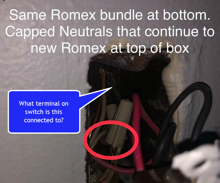
I am interested in this wire:
What terminal is that hooked into? Hopefully the common terminal. Based on the number of wires in your pictures power is either going to the fixture box first or the fixture is between the switches. Use a multimeter and put one probe on this wire and the other on the white wire of that same Romex which I assume is in the white bundle with the wire nut. See if that reads 120v if so that is power coming to this box first, if not then power is going to the fixture first.
Thanks @ritchierich
I opened the canopy on the fan, and here is what I see.
One 3wire coming from the ceiling and a total of 4 wire nuts with the following wires
wire nut#1 has a red cable and the blue cable (I assume the thinner blue cable connects to the fan?)
wire nut#2 has two black cables (I assume the thinner wire is connected to the light fixture through a terminal?)
wire nut#3 has two white cables (I assume the thinner wire is connected to the light fixture through a terminal?)
wire nut#4 has two greens
Am I missing something? This doesn’t seem to match the directions provided below
in fixture box:
Ok I was going off the fact you mentioned above that you have the “light” between the switches. If you only have 1 14-3 Romex in the ceiling box then you dont have this setup.
Please post clear pictures of your switch boxes with the switches pulled out so I can see all the Romex wires coming in.
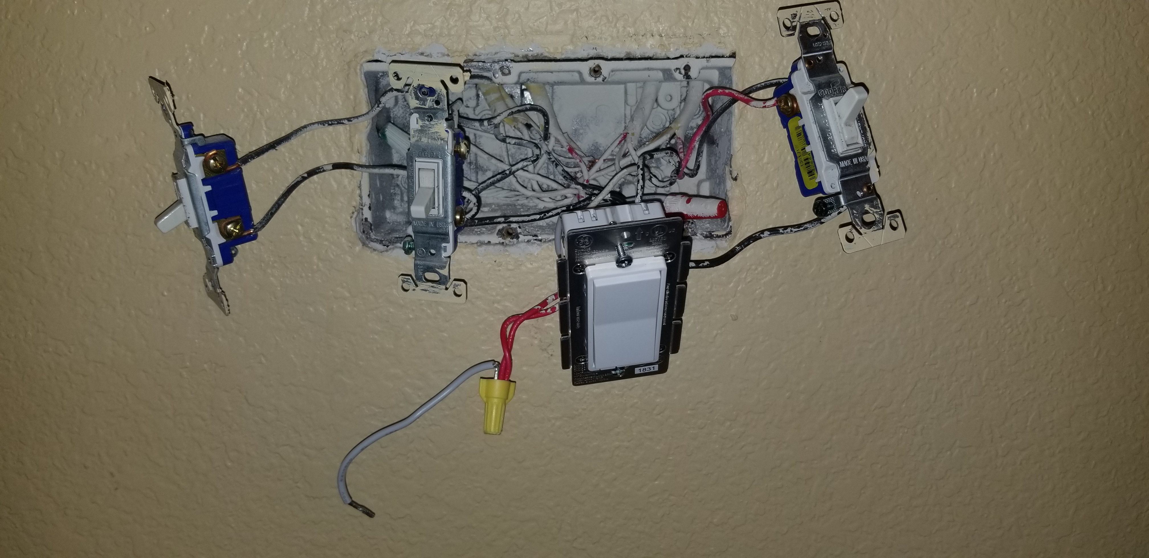
Thanks @ritch, so first, on the smart-switch side I’m dealing with a mess of box as it has 4 switches. From left to right in the graphic below
I don’t believe you need any details on the switches 1, 2, and 4, but let me know if you do.
From a separate 3wire, it’s cabled as follows to the smart switch:
The add-on switch is cabled as follows:
Reminder - cabled as explained above, I can turn the light on and off from the smart switch, but not from the add-on. Also note that my fan still works with switch#2 as explained above.
NOTE: With regard to switch#2 (switch that controls the fan on the ceiling fan), it’s connected as follows:
That black wire is going to the common. I will check this with a multimeter later today.
What is that white pigtail connected to these wires?
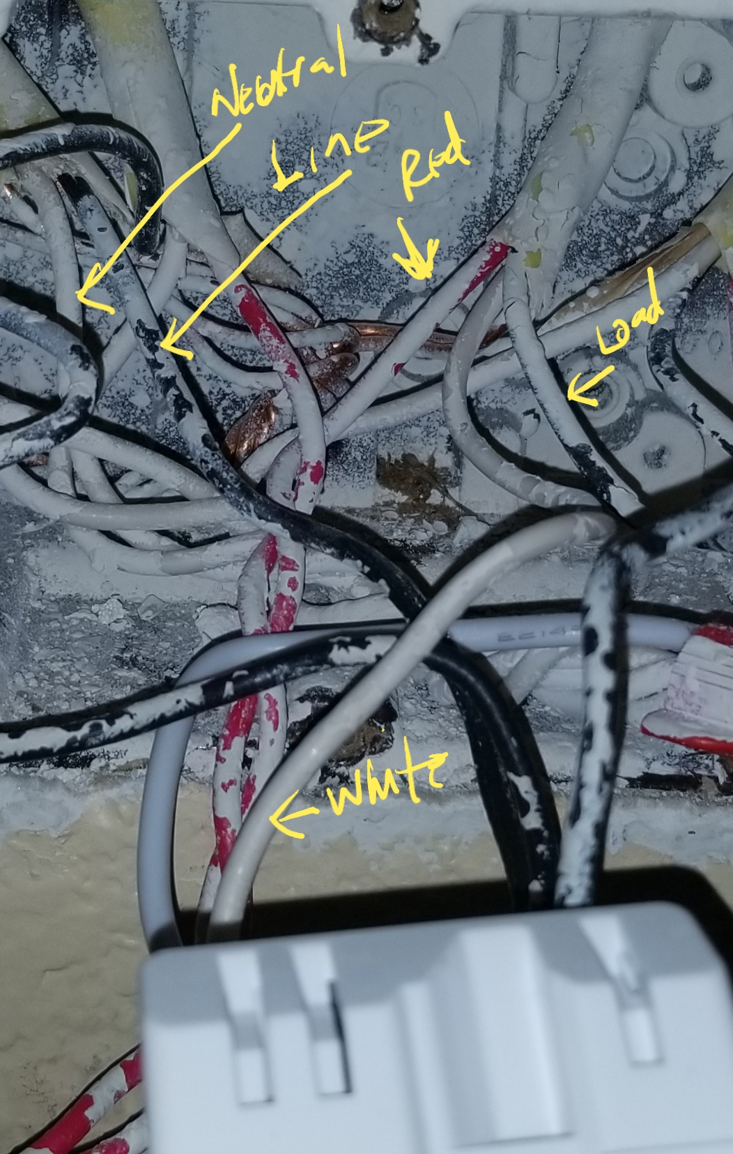
I have 2 14-3 wires circled and need you to confirm but believe I understand what’s going on:
Wire 1:
Is the black wire if this Romex hooked up to the second switch in this box that you sat is the ceiling fan? It’s hard to tell from the picture. If so follow along below, if not let me know and don’t follow ![]()
Again assuming that black wire of Romex 1 is hooked to your ceiling fan switch:
Wire 2:
Here is what needs to change:
Master Switch gang box:
Aux switch gang box:
That should do it
Later if you decided to smarten your fan, remember that the black wire of Romex 1 is your load.