My SmartThings hub V3 has a static IP address and my Arduino MKR1010 too:
I used your WIFININA sketch and only modified the IP addresses:
//WiFiNINA Information CHANGE THIS INFORMATION ACCORDINGLY FOR YOUR NETWORK!
//******************************************************************************************
String str_ssid     = "XXXX";                           //  <---You must edit this line!
String str_password = "XXXXXX";                   //  <---You must edit this line!
IPAddress ip(192, 168, 2, 61);       // Device IP Address      //  <---You must edit this line if using static IP!
IPAddress gateway(192, 168, 2, 1);    //router gateway          //  <---You must edit this line if using static IP!
IPAddress subnet(255, 255, 255, 0);   //LAN subnet mask         //  <---You must edit this line if using static IP!
IPAddress dnsserver(192, 168, 2, 1);  //DNS server              //  <---You must edit this line if using static IP!
const unsigned int serverPort = 8090; // port to run the http server on

// Smartthings Hub Information
IPAddress hubIp(192, 168, 2, 50);    // smartthings hub ip     //  <---You must edit this line!
const unsigned int hubPort = 39500;   // smartthings hub port


//Create a SmartThings Ethernet WiFiNINA object (comment/uncomment the lines below as desired - only ONE can be active)
//  static IP
st::SmartThingsWiFiNINA    smartthing(str_ssid, str_password, ip, gateway, subnet, dnsserver, serverPort, hubIp, hubPort, messageCallout);
//  DHCP
//st::SmartThingsWiFiNINA    smartthing(str_ssid, str_password, serverPort, hubIp, hubPort, messageCallout);
The output I get from Arduino Serial Monitor is this:
Enter the following three lines of data into ST App on your phone!
localIP = 192.168.2.61
serverPort = 8090
MAC Address = 2462ABB31B5C

SSID = XXXX
PASSWORD = XXXX
hubIP = 192.168.2.50
hubPort = 39500
RSSI = -41

SmartThingsWiFiNINA: Intialized

***********************************************************
***** SmartThings.send() - Ethernet Connection Failed *****
***********************************************************
hubIP = 192.168.2.50 hubPort = 39500
***********************************************************
******        Attempting to restart network         *******
***********************************************************

Initializing WiFi NINA network.  Please be patient...
Attempting to connect to SSID: Home

Enter the following three lines of data into ST App on your phone!
localIP = 192.168.2.61
serverPort = 8090
MAC Address = 2462ABB31B5C

SSID = XXXX
PASSWORD = XXXXX
hubIP = 192.168.2.50
hubPort = 39500
RSSI = -42

SmartThingsWiFiNINA: Intialized

***********************************************************
******        Attempting to resend missed data      *******
***********************************************************
***********************************************************
***** SmartThings.send() - Ethernet Connection Failed *****
***********************************************************
hubIP = 192.168.2.50 hubPort = 39500
***********************************************************
******        Attempting to restart network         *******
***********************************************************
I also tried resetting/reeboting my hub and router.
I am trying to get your example working without any code modification before going forward with my owm
What am I doing wrong?
It looks like you’ve done everything correctly to me. I just want to ask you one question, before digging in any deeper… By choosing to use the SmartThings On/Off example sketch, you are probably wanting to write your own sketch logic, as opposed to using the ST_Anything library, correct? I just want to make sure you didn’t somehow start with the wrong example…
Assuming you’ve chosen the correct sketch, everything else you’ve shown me looks correct. Have you tried a full power cycle of your ST v3 hub? I know that has helped others recently to get data flowing.
I assume you can ping both the ST Hub and the Arduino at 192.168.2.50 and 192.168.2.61 from another machine on the network?
And, are you the primary ST Account user, not a sub-account that has been granted privileges on the main ST account?
You are right, I want to build my own sketch logic.
I built a Temperature, PH and ORP meter for my pool, and now I want to send the values to SmartThings. Once the values are in SmartThings I’ll be able to program various stuff using WebCore.
I am also the primary ST account user.
I just tried updating my MKR1010 firmware version to 1.3 (it was at 1.0) but I still get the same result.
And finally, I unplugged my ST hub V3 for about 3 minutes and plugged it back in. Is it what you call a “full power cycle” ?
Hi
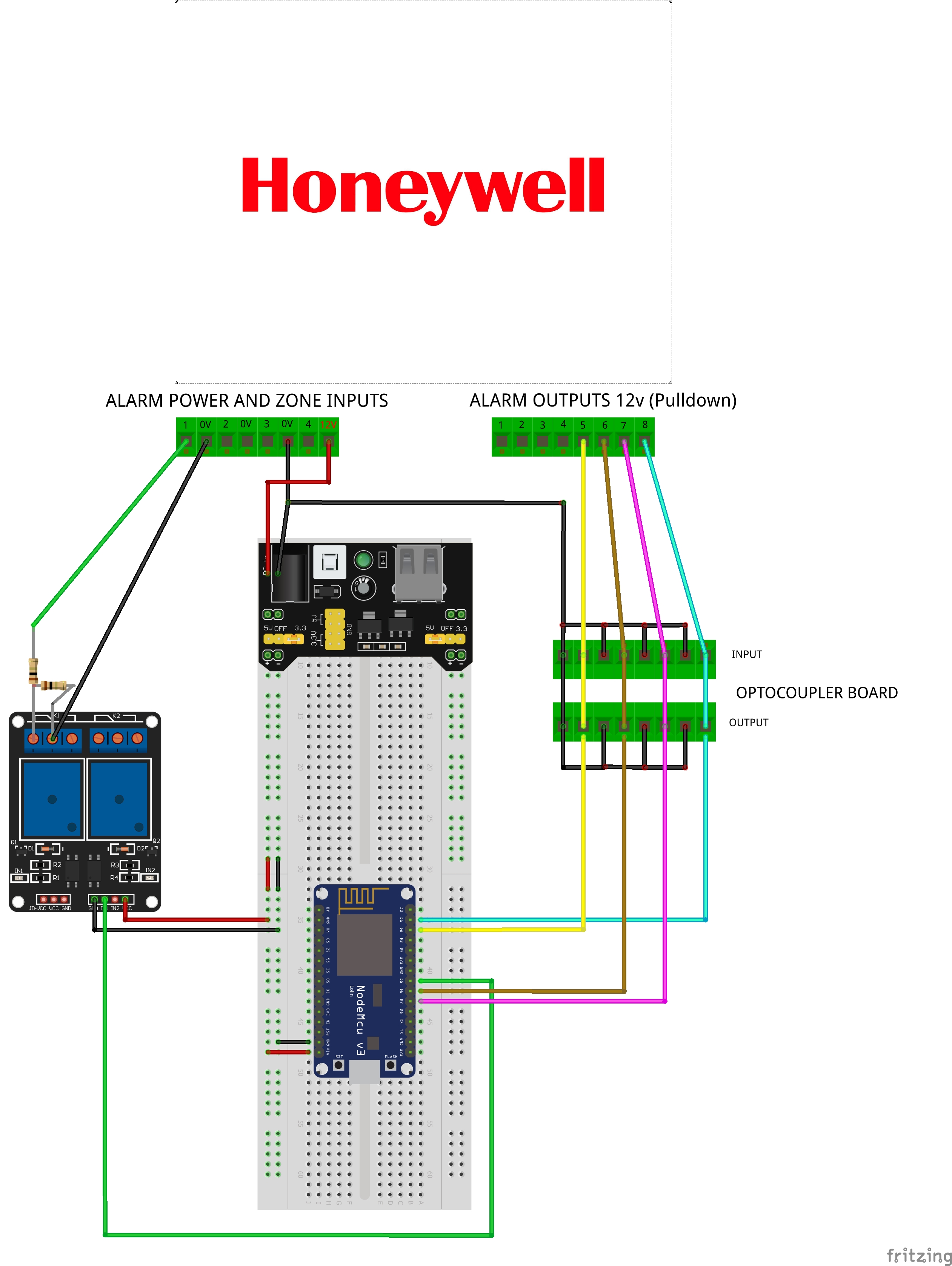
Thanks for you reply ive tried creating it on Fritzing like you asked for i’m not sure how good a job i’ve done as i’ve not used it before ha ha.
its a Jpeg as Fritzing doesn’t seem to allow project sharing at the moment.
The alarm outputs 5 & 6 are difined as motion sensors in my sketch and 7 & 8 as contact sensors and the relay is to activate a keyswitch on the alarm.
I can’t find the datasheet for it anywhere for the actual board. THIS is the one it says briefly on the description what you can run through it.
It’s uses the PC187 opto coupler
OK, based on this circuitry, I do believe the Internal Pullup feature should be enabled on the IS_Motion device declarations in your sketch. Please share what those lines look like in your sketch so I might be able to recommend any changes, if necessary.
Thanks for that.
i believe that’s what i have them set at.
i’ve noticed they have become a bit more responsive the longer i’ve left them i think i need to adjust the time it remains active.
this is the 2 lines i have .
static st::IS_Motion sensor3(F(“motion1”), PIN_MOTION_1, HIGH, true);
static st::IS_Motion sensor4(F(“motion2”), PIN_MOTION_2, HIGH, true);
Looks good to me. Not sure why there would be any delay in the motion sensors changing state… Of course, the Alarm panel is really what is in control of those, correct?
One other tip - I would recommend you change the wiring of your relay, slightly.
Here is an example of how I wire relays to a ESP8266 board, to optically isolate the ESP8266 from the Relay board, and to prevent pulling too much current from the ESP8266 to actuate the mechanical relays.
Note: This is for monitoring/controlling two garage doors. Just focus on the relay wiring. You have to remove the jumper on the 3-pin block to separate power for data signaling and relay actuating…
Thanks yeah its the alarm controlling the motion outputs.
doe’s this wiring look better for the relay based on your tip ?
What is it you have connected to D1 &D2 on your board?
I think to be safe, you may want to have resistor on the input side. Here is from the datasheet
Rd is needed. The value can be calculated. Without the resistor, the IR could sink too much current. On the other hand, the alarm side need to be able to supply enough current. I believe you should not have issue with this last point as most panel or gpio should not have issue to supply current for the LED side.
I am not sure that this is your issue. But, you may want to protect the LED side.
Optocoupler has some latency.
If your motion sensor pulses rather quickly, you can miss that. If you see the image above and image that the input pulse is so short, the output would not even change level. Again, you most likely does not have this issue as Alarm generally provide pulse duration that will be much larger than all those timing requirement of PC817. But, it is something to check.
To check whether those, you may need oscilloscope.
The ESP8266 has the INTERNAL PULLUP resistor feature enabled, which is what supplies the 3.3vdc to the Optocoupler (through the ~10K Internal Pullup Resitor). Thus, no external power supply or resistors should be required. At least that’s my understanding from how he has his board wired up, based on his Fritzing sketch.
Ah yes!!! On the 12V side of the optocoupler, there should probably be a current limiting resistor installed. I was focusing on the ESP8266 side of the optocoupler. Thank you for highlighting this.
Thanks @iharyadi@ogiewon
I need to look into this more then it seems.
Thanks for the info.
Yeah the 12v outputs from the alarm go directly into the optocoupler.
When using optocoupler, one want to isolate the circuit from one side to the other. Typically, you do not need the ground connected together. The Alarm side and the ESP side could be totaly isolated. On the output side, some relay does give separation between sides (the 12v and 3.3v of ESP).
sorry yeah they’re not actually connected i just couldn’t find the optocoupler on the Fritzing program so i just used that.
i’ve since found it and changed it now
Well, classic app has an end date now, Oct 14th. So I migrated one of my hubs over. The tiles and page layout are $hit but we already new that. Anyone work out how to get all the ST_Anything tiles units and Icons to display properly? I get the numbers but units and icons are wrong, among other things. Seriously, no more favorites screen and no variable color tiles
I know @vseven has made some pull requests recently to add units to some of the child DTHs. Make sure you upgrade those DTHs if you haven’t recently. Be aware, though, that if has been a long time since you updated the Arduino code, you may end up with a mis-matched set of code between the ST_Anything libraries and the ST DTH Groovy code.