Finally got all three H801 flashed and up and running! A HUGE thanks to @michaelahess for helping me get the flash process going. It really isn’t hard if you could see how all the cable connects are done. I ended up making a video to help out those like myself that have never worked with ESP firmware updates. I really needed something to hold my hand through the process so maybe this video will do that for someone else the way Michael did with me. (Firmware updating transfer starts around 7:00 in tutorial. )
Unbelievable awesome job @erocm1231 on the device handler and smartapps. So very impressive my friend! 
The first video I posted before the tutorial above. It doesn’t show all the details of setup but was intended to show what the flashing looks like on your computer when you are doing it successfully. Flashing starts at 2:15 in this first video.
All the links are in the description of video but I’ll relist them here for ease of use. If you go to any of @erocm1231 github repos for the SmartLife Devices or Sonoff Devices and you can grab the appropriate firmware bin file including the ESPeasy flashing software.
ESPeasy flashing software
http://www.letscontrolit.com/wiki/index.php/ESPEasy#Loading_firmware
Lixada H801 WiFi RGBW Controller
http://a.co/fLqTcKd
FTDI USB to TTL Serial Adapter
But you can use these non-genuine FTDI versions for less money and but see the photos to get the version on the left with FTDI on the backside that has been used successfully for flashing; the one on the right with YP-05 on the back has had reported issues.
http://a.co/dk8SEyI Amazon (I got this one but when you receive it make sure you received the version with FTDI printed on the backside) I ordered an eBay version which is also available on Amazon by the way UPDATE: DO NOT GET THE eBAY or Amazon (YP-05 version) the FTDI on the left is the one I got from Amazon in both pictures. You can zoom in and see the silk screening on the Amazon version is of higher quality being sharper with higher detail. On the back of PCB it says FTDI232 on the Amazon one and YP-05 on eBay version. Do not get the YP-05 version like I did from eBay as I continue to see reports of bad loads. Unfortunately sellers are not necessarily shipping what they say they are shipping depending on the inventory lot.


A slightly more expensive that has a genuine FTDI chip is this FTDI adapter by Adafruit.

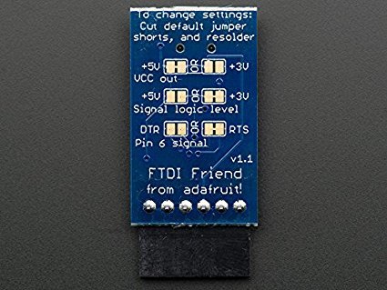
@MABeatty1978 says to make sure you have a soldering iron to change the voltage setting default on the Adafruit FTDI from 5v to 3.3v for the H801; no easy jumper to change here unfortunately. The official FTDI drivers you can download here at http://www.ftdichip.com/Drivers/VCP.htm and use the “Available as a setup executable” link in the “comments” of the Windows section.
Jumpers Wires Male to Male, Female to Male, Female to Female
Link: http://a.co/gxP6t0l
A couple tips I learned along the way when I had trouble flashing the device:
-
I originally got the Armorview PL2303HX USB To TTL To UART RS232 COM Cable Module Converter to do the flashing and had nothing but trouble; I couldn’t find the working driver necessary for making it work on Windows10 plus its fixed at 5v from the USB and the H801 needs 3.3v. I switched to using the FTDI board and it went great. I think the issues were due to the Amorview using a faked FTDI chip?
-
I had trouble flashing from my USB hub, switched to a direct connect to computer worked great.
-
It was easy to connect the wrong Tx, Rx pins and get them reversed.
-
Do not plug in H801 power supply adaptor when flashing. Have FTDI power the H801 (H801 VCC 3.3v from FTDI pin4 VCC) ** to minimize communication issues!
-
For some of the devices the jumper cables didn’t have solid connections to the board, they wiggled too easily. So I simply put slight pressure on the connections of cables by pushing them with my finger or even flipping the device upside down and letting gravity put pressure on the jumper cables the entire time I started the flashing upload.
-
Here is a picture of the parts I used for flashing and how I hooked them all together. The FTDI uses the “old” style mini-USB connector not the current micro-USB that most devices have today. I still had one from years ago that I put to use.
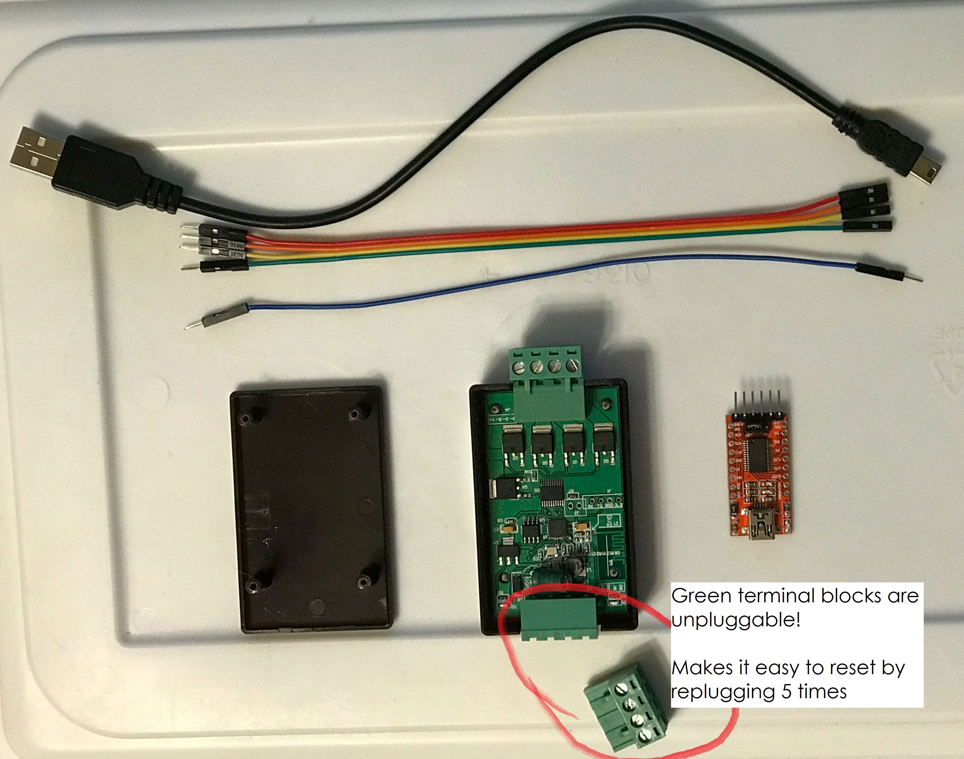
All the wiring connected as follows
here is a picture of my setup. I have a blue jumper wire on H801 J3. FTDI pin 1 and 5 left open. FTDI jumper is set on 3.3v
H801 Rx to FTDI pin2 Rx
H801 Tx to FTDI pin3 Tx
H801 3.3v to FTDI pin4 VCC **Have FTDI power H801 to minimize communication issues!
H801 Grd to FTDI pin6 Grd
FYI, the photos are high resolution so you can zoom way in to see the connections and wiring up close.


Just testing out using a single H801 for controlling my super bright double row LEDs for the under cabinet countertop lighting on channel W2 and the RGBW which is for the top of the cabinets. It works like a champ!

Just for clarification since the photo isn’t clear here; I had to extend the white wire of the RGBW strip by soldering a small piece of white wire and I shrink wrapped it so that it could go to the other side of the H801 and get terminated on the W1. Then I had to do the same thing with the black wire of the dual White LED strip and extend it using the brown wire and terminated on W2.