*** I have left most the original from the top down. However, near the bottom of the main post you can see I’ve made alot of changes and show the transformation from then to now… I did however remove the original video and updated it on 09142018
I’ve seen a lot of posts lately asking about pool pumps, lights, temps, and valves etc. These questions are being asked a lot because there isn’t a lot of information or products out there that work with this kind of thing. When I moved in I got a quote from a pool guy to automate the pool valves and they told me that it would be at least a grand to automate pool stuff and I don’t even think that would have been that powerful or integrate-able into smartthings. After a while I decided that I like and enjoy DIY projects and this could be some fun. I didn’t understand arduino programming when I started and the whole realm was really intimidating but figured I could learn as I went by reading on the web asking questions on forums watching videos etc. Anywho I have decided that my DIY pool controller has hit a level far enough that it is worth sharing. This project has come a little at a time and so far does: Variable Speed Pump Control, Outside Air Temperature, Power Use, Valve Control, Pool Light Color Control, Pool Water Temperature, Pool Water Level, Automated Water Fill Valve, and Water Use. In the future I envision it growing into possible PH sensing and chlorine sensing with automatic dispensing for a completely hands free pool.
The first part of the project and the brains of the operation is a particle photon which is a wifi arduino that is extremely easy to work with. This controls an 8channel relay with octocuppler so that it can work with mixed voltages with no mixing of the voltages. I have 24 volt AC pool valve actuators and and also 12 volt DC ball valves. The 120 volt pool light also connects to the relay board.
So all 8 channels are used as follows for me
ch1 floor cleaner valve on 24vac
ch2 floor cleaner valve off 24vac
ch3 pool aerator on 12vdc
ch4 pool aerator off 12vdc
ch5 pool pump speed control 12vdc
ch6 pool pump speed control 12vdc
ch7 pool pump speed control 12vdc
ch8 pool light 120vac
The pool pump has 8 selectable speeds based on combinations of on or off from the three relays and these combinations were right in the manual for my hayward tristar 3202 vsp pump so there was no trial and error required to figure out their relay control.
I also have a Ds18B20 temp probe for measuring outside error temp and sensing a value to smartthings every ten minutes.
The pool light I purchased cycles colors when turned on and off quickly this made it easy to program color selection within the photon.
The second part of the project is the water valves. I have ball valves and flow sensors hooked to a second battery backed up photon so that water valves don’t get left on in the event of a power outage and I can measure and dispense calculated amounts of water. I also hooked my patio misters up to this same photon with a y splitter at the water spiggot so I can also turn on my patio misters.
The third part is a battery powered sesnor I made from a third photon that has a vl53lox laser distance sensor for pool water level and a ds18b20 temp probe for pool water temperature. This all tucks neatly under a skimmer basket lid and wakes up every 4 hours to send a new reading then sleeps for energy conservation.
I have attached a quick video of the whole schebang in action. Cheers!

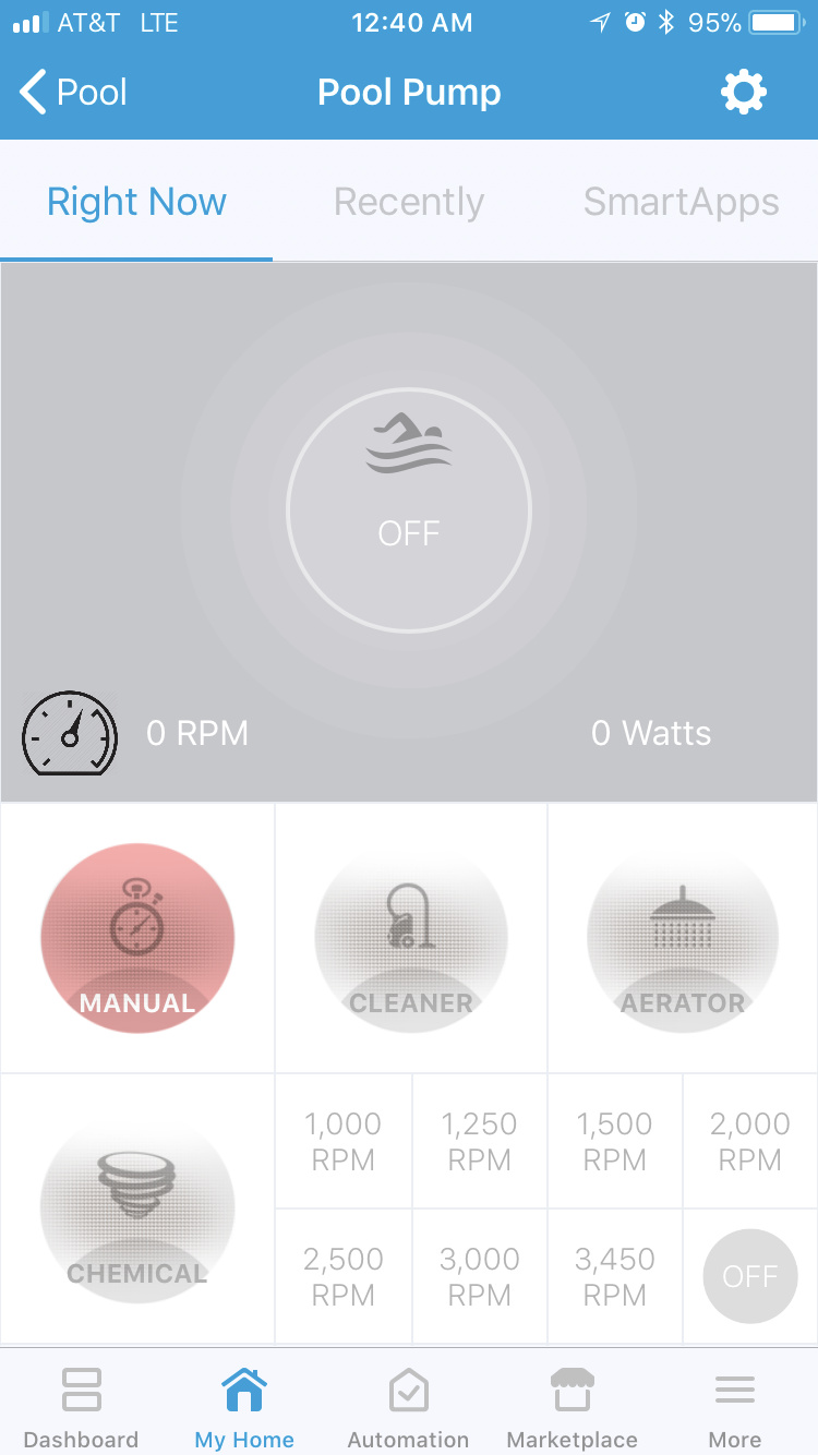
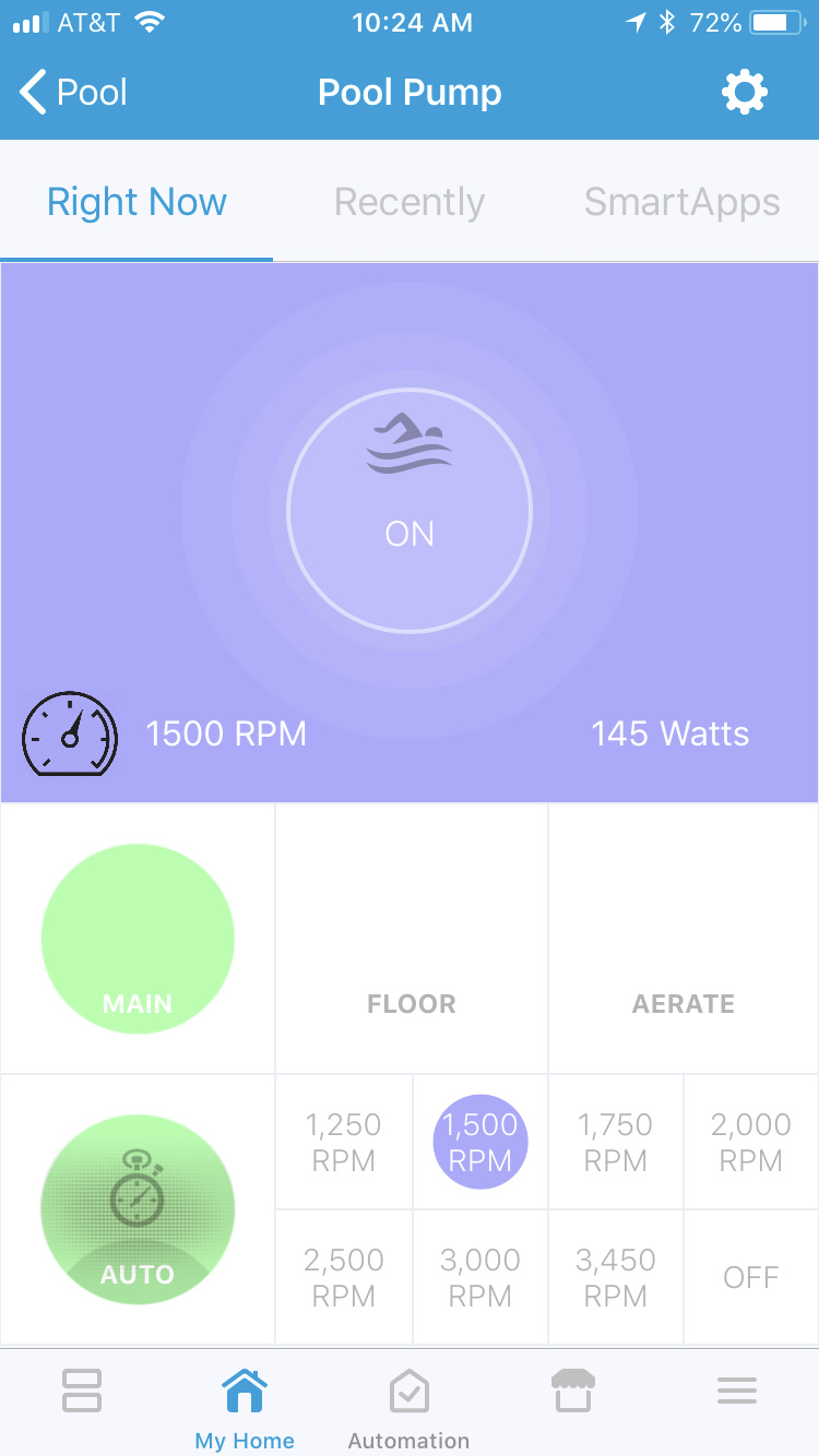
Here’s a screenshot of my device handler and action tiles pannel for the pool.
*** edit I have edited the device handler to a new look…
*** second edit I added the ability to control my valves all from the one device now and included optional virtual switches to stir chemical for set time


Action Tiles

And the Swimming Pool Light Controller.

The garden hose device type works as a dimmer and has gallons dispensed from the flow sensors. This is part of the auto-fill system

Any of the code used to get it going is posted here…
For my normal pump run schedule control and refreshing I use webcore to tie all of it together… basically anytime you see a particlepublish in my code its triggering a webhook to refresh a device in webcore
EDIT**** I’ve added this little video showing the guts and conceptually explaining the wiring. Not wire by wire but should give you a good idea of what I did. I also am adding this little blurb to kind of supplement the video
Okay lots of people have asked about the wiring I’m not sure how to go about it so unless i drew a bunch of schematics and did it wire by wire there is no good way to show this but I am updating the original post to include a video showing the guts of each thing. I tried to kind of describe the wiring and parts conceptually with the video but this isn’t going to have every wire or anything as I’m sure it will be a mess and hard to tell or remember for that matter so I’ll just assume a basic understanding of electrical stuff and show what I did. But its important to realize that there isn’t a one size fits all approach to wiring since everyone’s pool equipment pad may be different. I’ll use this writing to kind of supplement the video.
The main pump controller I have a gfci outlet on my pool equipment pad. Downstream of this so everything is GFCI protected I added the three tap electrical chord. This has two things plugged into it 1) a 24 volt ac transformer to control the jandy valves. I send one leg of this to the relay first pig tailed so i can split it and send it to two relays one for open one for close if you have more jandy valves you obviously would have more in your pigtail. 2) a 12 volt one amp dc power supply I pigtail the positive leg of that 6 ways. One leg goes to my step down usb converter power supply thing (not a technical term) basically it takes the higher voltage ie 12 and steps it to five volts clean usb power supply to supply the photon I did this so I didn’t have to have yet another power supply plugged in. I found that board on amazon. The other 5 wires from my pigtail go to the relay board one for open of my 12volt valve and one for close of the 12 volt valve and the other 3 go to the relays for pump speed control. The pump speed control didn’t require 12 volts there was a whole acceptable range of power it could sense this is just what I used since I already had a 12 volt source. The 8th relay is my pool light the power source is 120 volts again from downstream of the gfci outlet so my pool light is also gfci protected. I don’t think I showed it in my video but the relay board itself is powered from the 5 volt pin from the photon. I also have the outside air temp probe on there I forgot to show but it is powered from one of the digital pins on my photon I cant remember which one you would have to refer to my code.
As far as the temp level sensor the laser distance sensor on mine is able to be powered with anything from i think 2.8 volts to 5 volts so I just power it again with a digital pin from my photon which is a 3.3 volt source. the temperature probe is also powered from one of the digital pins. The photon itself is powered from an 18650 battery that first it goes to a lithium charging board I got on amazon in a five pack for like 2 bucks. Its a simple circuit the only other things I added was a power switch to turn it on and off and the 4.7k resistor that is required for the temperature probe to function properly.
The water valves and flow sensor setup is powered from an 1860 lithium battery again so it can continue in a power outage and not leave valves open and water on. On the input side of that charger board I have a 5 volt dc power supply so it runs off mains power keeping the battery topped if their is power. Outflow from that is split up one side goes to a step up usb buck converter I have that takes the lower voltage output from the battery and steps it up to a clean 5 volt usb supply for the photon. The other side of that goes to the boost converter to step up the voltage to 12 volts for the valves. This is then switched at the relay to open and close valves. The relay board itself is powered off the 5v pins on the photon. The 5 volt pins on the photon also supply power to the flow sensors that require five volts to run.
Hope this helps!

**** edit 5/24/18
Okay so for everyone following this project I finally found some time to tinker and I have incorporated a whole lot more into my project. The changes are as follows.
-
I cut out the old abandoned water line and plumbed right into my old autoflll line so there is no more hose in the pool but a dedicated line that my photon turns on and off to dispense and measure water directly into the pool. Big improvement getting rid of the eye sore of a hose.
-
Changed my jandy valve to actually have three way programming now using two relays. This allowed me to shut off all main returns and only send water to the aerator allowing me to run the aerator at a way lower pump speed and consequently save money. Here in phoenix in the summer I have to run my aerator alot to keep the pool cool. Because the aerator line is so small I put some pump speed protections coded in to keep from accidentally putting too much pressure into the small 1/2 inch line. Changed my device handler to show an intuitive three way valve to match my three available positions of main returns floor cleaners and aerator only.
-
The aerator valve itself, which is the 12 volt 1/2 inch ball valve style valve, I decided after some tinkering that I only needed full open or closed and no intermediate positions. Therefore I freed up a relay by changing my code and wiring the close to the NC position and the open wire to the NO position on a single relay instead of two. Now I’m either full open or close.
-
The biggest and most exciting change is chemical injections. I have added two 15 gallon chemical drums with stenner peristaltic pumps. One for muriatic acid since my pool ph creeps up and a second for liquid chlorine. I hate flaoting the pucks as they add too much stabilizer to the pool rendering the chlorine useless. I wont get into cynaurics here but I’ve been manually dosing my pool with liquid chlorine daily or every other day or so. If you are interested in why checkout www.troublefreepool.com since following the practices here my pool is always sparkling clear and cheap on the chemicals. Obviously I wanted to get this process automated as work will keep me gone more this summer than normal making it so I cant dose the pool. To set this up I needed two relays and I only had one left on my 8 relay board. Good news is I had a single relay kicking around I used to tinker with projects. So I wired that up to my photon and I was good to go. My wiring method on these was I took out the gfci outlet on my pool sub pannel and instead put a gfci breaker on the circuit. I then took a regular outlet and snipped the brass jumper conncetor thing on the hot side which separates the top outlet from the bottom. Now I hooked up each outlet to my relays. This just allowed me to plug the stenner pumps right into the now controlled outlets instead of modifying the pumps chord and possibly voiding warranty. This also looks cleaner. For the pumps run schedule I figured that I could afford no errors here and therefore did not want to rely on smartthings for scheduling as if a pump failed to shutoff i could pump way way too many chemicals into the pool. SO for the scheduling I handle it locally on the photon. My device handler for the chemical pumps just merely shows which pump is on or not and also allows me to change the daily targets. And I can also set a manual run with a timer that is also internally handled once the request is received.
-
Running the stenner pumps locally as well as the discussions above where some of you thought that the pump and valve schedule itself would be better run internally rather than relying on webcore for my regular pump schedules got me thinking that I might as well program my pump and valves internally as well. So that is what I did it was easy to do now smartthings shows whats happening and I can manually over ride but I have an automatic mode that internally schedules its own runs then just refreshed the device in smartthings to show its current state. This overall should make the whole thing more reliable. The aerator also is decided locally if it should run based on time of day and water temperature.
I’ll attach a video and some pictures below. As far as looking into the future I’d like to maybe incorporate a variable run rime that automatically adjust seasonally be it by month outside air temperature or pool water temp. This would eliminate any need to change the schedule seasonally making it a truly smart pool controller. Other ideas I’ve tossed out is smartthings sending a high wind warning to the the photon to run a little extra speed or duration on the floor cleaners. I’d still also consider adding chemical sensors if I can find a good reliable and cheap way to do it. It would incorporate nicely with my auto injectors as right now Ill just have to guess and approximate the time and periodically test the pool.


*** edit 09142018
So I have done alot of updates even though I haven’t been in here to keep up on it. So I thought I would update the main video at the top of the page as well as talk about a couple of things here.
-
Particle firmware 0.7.0 is riddled with lots of connectivity bugs. This made me think I was having network hang issues etc that lead to several coding changes. I’ve since found out its bugs in 0.7.0 but my changes are still good changes nonetheless. For instance I found that if network is lost it causes the loop to hang long enough I was missing some local events. So now I have taken control of network control in my firmware. if connectivity is lost it will move on and work on regularly scheduled events and checkback every minute or so and try to connect for a few seconds and if it fails it moves on so it doesn’t hang up trying to connect and miss important jobs. I added an RSSI variable so you can see how your connection is. However, mainly either run 0.6.3 or the new prereleases im on 0.8.0 rc.10 and its working great… in fact particle even incorporated a device health feature and disconnect counter in the new pre-releases. But do not run 0.7.0
-
The automode now runs as a resume function for instance if you make a manual change and then re-engage auto mode it goes back to where it should be locally scheduled. The same happens if you have a power outage or the device gets rebooted it resumes the regular scheduled speeds and valve settings instead of waiting for the next event.
-
I had the LED for the pool light burn out eventually and I got a new one. I was surprised it didn’t last longer but oh well the new bulb which was the same kind from amazon has had some changes to how it color cycled so I had to incorporate the changes into my coding… I took this time to clean it up and make the color changing code one small function instead of a large function for each color.
-
Level sensor eventually died to corrosion. I need to either get a case printed to protect it from the elements or go a different direction with the design. The photon and temp sensor portion are fine since they weren’t directly exposed.
Cheers…
 that’s definitely the next step this year I want to get ph measurement and colorine measurement and possibly dispensing.